PAPER No. 2
High Bandwidth Armature Current Regulation of a Cold-Rolling Mill MG-Set with Parallel 12 Pulse D-C Bridge at Inland Steel
AISE Annual Meeting
Brian Thomas Boulter
Applied Industrial Control Solutions LLC
4597 E Sprague Rd.
Independence, OH, USA 44131
© ApICS ® LLC 2000
Abstract: A high bandwidth armature current regulation scheme for an MG-Set that is operated in parallel with a 12 pulse DC bridge is presented. The regulation scheme regulates armature current via a reference to the generator shunt field current regulator. A self-tuning generator shunt field current loop that approximately compensates for the effects of generator eddy currents is described. With the described armature current loop, higher bandwidths enable the implementation of inertia and backlash compensation schemes that translate into significant improvements in speed loop tracking and bandwidth notwithstanding limitations imposed by a mechanical drive train with a low torsional natural frequency and significant backlash.
1. INTRODUCTION
Investment in the present installed base of applications employing MG-Sets is adequately significant to justify upgrading the existing control systems rather than scrapping the MG-Set generators and installing new DC static drive systems. Upgrades of existing systems may become necessary from market pressures to improve product quality, or it may result from a need to realize an improvement in system reliability and consequently, productivity. Typically these upgrades are performed in the field during several short shut-downs. The 5 stand cold rolling mill at Inland Steels' Indiana Harbor works underwent such a field modernization. The objectives of this project were 1) to improve product quality with an AGC upgrade, 2) to reduce scrap with improved speed loop tracking during accelerations and decelerations and 3) reduce down time for control system maintenance.
Before describing the current minor loop (CML) implemented at Inland Steel, a brief synopsis of control strategies employed in MG set applications commissioned circa. 1950 to 1975 is presented. While this brief overview may be unnecessary for the "old hands" of the industry it will be useful for younger engineers who have not been exposed to MG-Sets in their academic curricula.
Control topologies in MG_Sets applications can be condensed to three basic design strategies. The first strategy employed mag-amps (an "amplidyne" configuration for low power applications is presented in Fig. 1). The output voltage of the "amplidyne" is controlled by the field current through the control winding. By supplying current to the field winding, generator action causes a voltage to develop across both pairs of commutator brushes. One pair of brushes is shorted so that a large current occurs in the windings connected to these brushes. The other pair of brushes is connected to the load through a compensating winding. The windings are arranged so that the strong magnetic field developed by the shorted pair of brushes reinforces the control field excitation. The power delivered to the load is therefore, an amplified function of the signal applied to the control winding. Mill stand MG-Sets applied the mag-amp configuration for the control of generator field current which in turn controlled generator voltage.
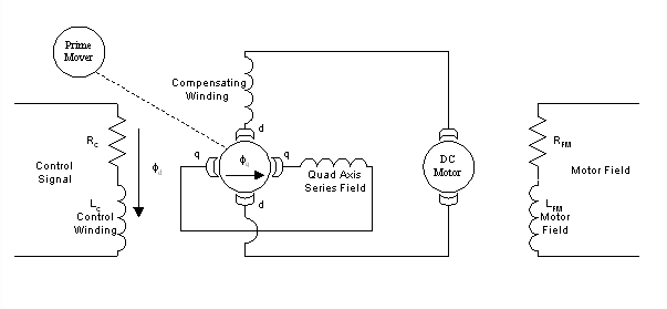
Figure 1. A Low Power "Amplidyne" Controlled MG-Set
The second design strategy centers around armature voltage regulation (Fig. 2). Armature voltage is a function of the generator shunt field flux which is itself a function of the shunt field current. Armature voltage regulation may be achieved by controlling the firing angle of the generator shunt field power module (and consequently the generator shunt field current) with the output of an armature voltage regulator. Change in shunt field current results in change in shunt field flux and consequently armature voltage.
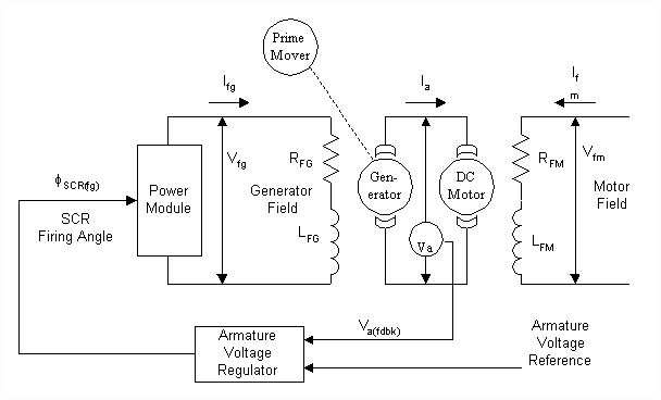
Figure 2. Armature Voltage Controlled MG-Set
The third design strategy employed armature current regulators Armature current regulators were implemented in much the same way same as the armature voltage regulator in Fig. 2 but with the substitution of armature current feedback for voltage feedback. In both the second and third control strategies the power module providing generator field current is effectively run open loop. Differences in linearization techniques are the most noticeable contrasts in the control schemes of drive vendors who applied the above three strategies.
During the 1960's and 70's speed regulation became more common in cold rolling mills as the quality of interstand tension measurement devices improved and AGC algorithms were developed that controlled interstand tension. These algorithms required individual mill stand speed regulation. In the early speed regulation schemes the speed error was used to provide the generator field power module firing angle in much the same way as the voltage error in design 2 above. Later approaches employed a current minor loop (CML) as described in design 3 above, with a cascaded speed loop, in a manner similar to modern static drives. Despite claims to the contrary the speed loop bandwidths of these systems were typically around 5 [rad/sec]. Performance is severely limited by the electro-magnetic characteristics of the generator field and armature. Drive trains with low torsional natural frequencies and significant backlash imposed additional constraints on the speed loop bandwidth.
More recently, digital and/or analog static DC drives have been designed with self-tuning CML's. The CML is readily modeled as a lag from the current reference to motor torque with a fixed gain and a corner frequency approximately equal to the CML bandwidth. CML bandwidths for these drives can vary from a low of about 100 [rad/sec] to a high of several thousand [rad/sec]. The high bandwidth of the CML ensures that the factors limiting speed loop bandwidths in static drives are attributable either to the mechanical configuration and/or the speed loop control strategy employed. In static drives the bandwidth of the inner loop rarely imposes limitations on the performance of the speed loop.
The armature CML presented in this paper differs from older designs in two ways: 1) The use of a generator field current regulator 2) The implementation of a stiffer CML control algorithm. It will be shown that the small signal response of the rotating CML described in this paper (Fig. 3.) is very similar to that of a static CML with a bandwidth of 50 - 100 [rad/sec]. Because of this, DC static drive speed loop design strategies may be utilized including backlash compensation, inertia compensation, and frictional loss compensation. The net result is a significant improvement in speed loop bandwidth and tracking. In the case of the 5 stand cold rolling mill at Inland Steel the higher bandwidth of the CML and the resulting improvement in speed loop response (around 12 - 15 [rad/sec]) combined to produce a significant reduction in scrap along with improved AGC regulation.
The MG-Set CML regulation scheme in Fig. 3 and its associated tuning algorithm are described in section 2. In the application at Inland Steel an additional complication includes a 12 pulse DC bridge that is wired in parallel with each MG-Set armature and supplies additional armature current during mill acceleration and rolling. Because the bridge is non-regenerative it does not contribute to armature current during deceleration. As a consequence of these differing operating conditions, a scheme was implemented to ensure a stable sharing and transferring of load between the MG-Set and the 12 pulse bridge as a function of the magnitude and sign of the current reference. This scheme is described in section 3. In section 4 a simulation of one stand from the cold rolling mill at Inland Steel is compared to results obtained on-site. Section 5 closes with some observations and conclusions.

Figure 3. Armature Current Controlled MG - Set
2. MG-SET CML REGULATION SCHEME
2.1 BACKGROUND:
Recently, mill-model based closed loop AGC control algorithms have been installed in rolling mills. These algorithms require speed loop bandwidths in the range of 10 to 25 [rad/sec] to realize significant improvements in gauge control. Speed reference tracking of each stand in the mill must be approximately equal to minimize disturbances to the AGC during line accelerations and decelerations. With these requirements in mind the following control algorithm was developed for MG-Set applications.
2.2 NOMENCLATURE
|
s |
The Laplace operator |
|
VM |
Rated motor armature voltage [V] |
|
IM |
Rated motor armature current [A] |
|
RM |
Hot motor armature resistance [mW] |
|
LM |
Hot motor armature inductance [mH] |
|
ZM |
RM + s LM |
|
w M |
Rotational motor speed [rad/sec] |
|
VFM |
Rated motor shunt field excitation voltage [V] |
|
IFM |
Maximum motor shunt field current [A] |
|
RFM |
Motor shunt field resistance [mW] |
|
LFM |
Motor shunt field inductance [mH] |
|
t FM |
LFM /RFM Mot. shunt field elec. time const. [sec] |
|
EG |
Generator open terminal voltage [V] |
|
IG |
Generator armature current [A] |
|
RG |
Generator armature resistance [mW] |
|
LG |
Generator armature inductance [mH] |
|
ZG |
RG + s LG |
|
KG |
The generator "gain" |
|
w G |
Rotational generator speed [rad/sec] |
|
VFG |
Rated generator shunt field excitation voltage [V] |
|
IFG |
Rated generator shunt field current [A] |
|
RFG |
Generator shunt field resistance [mW] |
|
LFG |
Generator shunt field inductance [mH] |
|
NFG |
The number of turns in the Generator Shunt Field |
|

|
The generator shunt field flux [Wb] |
|
REG |
Effective gen. eddy current circuit resistance [mW] |
|
LEG |
Effective gen. eddy current circuit ind. [mH] |
|
IEG |
Generator eddy current [A] |
|
t FG |
LFG /RFG Gen. shunt field elec. time constant [sec] |
|
t E |
(LA+LG) /(RA+RG) MG-Set elec. time constant [sec] |
|
ES |
12 pulse bridge open terminal voltage [V] |
|
IS |
12 pulse bridge current [A] |
|
RS |
12 pulse bridge terminal resistance [mW] |
|
LS |
12 pulse bridge terminal inductance [mH] |
|
ZS |
RS + s LS |
|
IMAX |
Maximum operating current [A] |
|
LIM |
IMAX/IM |
|
w C |
Armature CML PI lead freq. [rad/sec] |
|
w CML |
Desired Armature CML bandwidth [rad/sec] |
|
w FML |
Gen. shunt field current reg. bandwidth [rad/sec] |
|
w RLD |
Armature CML ref. lead/lag lead freq. [rad/sec] |
|
w RLG |
Armature CML ref. lead/lag lag freq. [rad/sec] |
|
w FLD |
Armature CML fdbk. lead/lag lead freq. [rad/sec] |
|
w FLG |
Armature CML fdbk. lead/lag lag freq. [rad/sec] |
2.3 MG-SET CML CONTROL ALGORITHM :
A popular block diagram representation of a generator with a shunt field is given in Fig. 4 [6]. This representation is valid under the assumption that the magnetic paths for the eddy current circuits and the field winding circuits are approximately the same and are ideally coupled. This is typically not a valid assumption for industrial machines [1], [3]. In these machines the magnetic coupling between the field poles and the motor frame is composed of a multiplicity of circuits with vastly differing magnetic coupling coefficients. This phenomena can be attributed to many factors the most dominant of which is the geometry of the stator, motor frame and field poles. Differences between the dynamic performance of an industrial generator and models developed under the above assumption may be significant in machines with extremely non-linear magnetic coupling, however for the sake of brevity this assumption will be used in the following analysis.
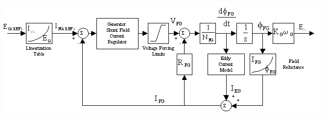
Figure 4. Generator Field Current Loop Model
Given that:
 ; and : ; and :  ; [1] ; [1]
An approximate linear representation of Fig. 4. can be constructed for a given flux and is shown in Fig. 5. The quantities LEG and REG are not easily quantified, they may be obtained experimentally or they may be deduced from motor electro-magnetic models. Solid frame motor vendors develop proprietary motor models based on their respective motor geometries. These models also yield approximations of eddy current effects. Rough estimations of LEG and REG may be obtained from reducing these models.

Figure 5. Linearized Generator Field Current Loop Model
The linearizing table acting on the reference to the generator shunt field current regulator equates steady state terminal voltages with steady state generator shunt field currents. This table can be generated empirically with some simple measurements made on-site.
For the approximate linear system in Fig. 5:
 (1) (1)
 (2) (2)
 (3) (3)
solving for EG/VFG in the Laplace domain yields:
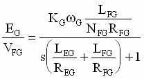 (4) (4)
Equation (4) shows clearly that even in the ideal linear model the lag attributable to the shunt field winding RL circuit is lowered by eddy current phenomena. A proprietary self-tuning generator shunt field current minor loop (FML) algorithm approximates shunt field reluctance as a function of current set point from which shunt field inductance may be calculated. A regulator structure that is based on a PI implementation with feedback forcing (a lead/lag in the feedback) is then self-tuned to provide an approximately consistent FML bandwidth over the expected range of generator shunt field flux and shunt field df/dt. The FML may now be tuned for a desired bandwidth and modeled as a lag at the FML crossover frequency. Field testing has shown that in solid frame motor applications, the FML bandwidth of this regulation scheme varies by less than +- 20% of the desired value when operating within the voltage forcing limits of the generator shunt field current regulator power module.
An open loop linear armature voltage regulator can now be created using the linearization table and the closed FML (Fig. 5). Large signal eddy current effects and armature reaction in solid frame generators that do not have armature reaction compensation windings can significantly alter the dynamics of the FML ([1],[2],[3]). For small signal analysis these effects may be ignored and the transfer function from  to to  can be approximated as a lag with a corner frequency equal to the bandwidth of the FML regulator, as described above. In the Reliance Automax control environment this is approximately 100 [rad/sec]. This is a major divergence from previous designs where the lag attributable to the generator shunt field was approximated as 1/ tFG, typically a lag of 0.5 to 5 [rad/sec]. This difference in regulation approaches acquires considerable significance when looked at from the point of view of pole-zero cancellation. If an MG-Set CML algorithm attempts to utilize a forward path lead frequency in the CML regulator to cancel the pole at 1/ tFG the combination of forward path low frequency pole-zero cancellation and a desired closed loop bandwidth greater than 10 times the canceled pole frequency will result in extremely poor loop performance when saturation effects are considered ([4] [5]). In MG-Set applications the single most significant saturation element is attributed to the voltage forcing limits imposed on the FML by the shunt field power module AC supply voltage (Fig. 4). The use of feedback forcing as demonstrated in [4] results in a much more robust solution and was employed in both the FML and CML loops. can be approximated as a lag with a corner frequency equal to the bandwidth of the FML regulator, as described above. In the Reliance Automax control environment this is approximately 100 [rad/sec]. This is a major divergence from previous designs where the lag attributable to the generator shunt field was approximated as 1/ tFG, typically a lag of 0.5 to 5 [rad/sec]. This difference in regulation approaches acquires considerable significance when looked at from the point of view of pole-zero cancellation. If an MG-Set CML algorithm attempts to utilize a forward path lead frequency in the CML regulator to cancel the pole at 1/ tFG the combination of forward path low frequency pole-zero cancellation and a desired closed loop bandwidth greater than 10 times the canceled pole frequency will result in extremely poor loop performance when saturation effects are considered ([4] [5]). In MG-Set applications the single most significant saturation element is attributed to the voltage forcing limits imposed on the FML by the shunt field power module AC supply voltage (Fig. 4). The use of feedback forcing as demonstrated in [4] results in a much more robust solution and was employed in both the FML and CML loops.
It should also be noted that the amount of voltage forcing available for the FML will also impact the range of  over which the FML is linear. The more forcing the greater the range. For this reason it is desirable to have voltage forcing greater than two. A forcing ratio of four is desirable but not often practical. over which the FML is linear. The more forcing the greater the range. For this reason it is desirable to have voltage forcing greater than two. A forcing ratio of four is desirable but not often practical.
Modeling the transfer function from EG(REF) to EG in Fig. 4 as a lag, the following block diagram (Fig. 6.) of the CML in a locked rotor condition may be constructed. The regulator section is presented in a per-normal representation.

Figure 6. Locked Rotor MG_Set Block Diagram
A loop shaping approach is taken when tuning the CML. The objective of the design is to produce a closed loop CML that effectively looks like a 2nd order low pass filter that is 3 [db] down at wCML. Excessive high frequency noise in the armature current that was attributable to the firing of the 12 pulse DC bridge SCR’s made the second order roll-off desirable in this application
Assume the following gain and ratios of frequency compensation tuning values to the desired CML bandwidth (6), are applied to the open loop transfer function (5) (without the inclusion of the lead pre-filter).
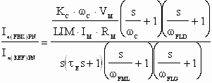 (5) (5)
CML Tuning Parameters
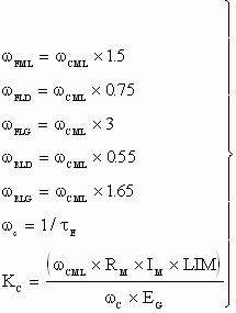 (6) (6)
A set of four open loop Bode plots may then demonstrate the design strategy for a reasonable range of electrical time constants and deviations of  . They are presented in Fig. 7. Following is a tabulation of the four conditions ( . They are presented in Fig. 7. Following is a tabulation of the four conditions ( = 50 [rad/sec]). = 50 [rad/sec]).
|
Plot |
 [sec] [sec]
|
 [rad/sec] [rad/sec]
|
|
1 |
0.01 |
0.8 /tE |
|
2 |
0.01 |
12 /tE |
|
3 |
0.1 |
0.8 /tE |
|
4 |
0.1 |
12 /tE |
Table 1.
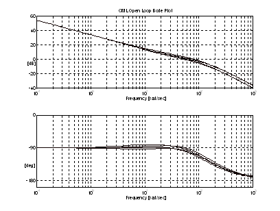
Figure 7. Open Loop Bode Plots; For  = 0.01, and 0.1[sec] and wC= 0.8/tE and 1.2/tE = 0.01, and 0.1[sec] and wC= 0.8/tE and 1.2/tE
Assuming wC= 1/tE and using the gain and ratios in (6), the closed loop transfer function of (5) is:
 (7) (7)
Approximately factoring (7) and including the lead pre-filter yields:
 (9) (9)
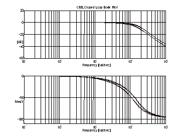
Figure 8. Closed Loop CML Bode Plot (Inc. the lead pre-filter). For tE = 0.01, and 0.1[sec] and wC = 0.8/tE and 1.2/tE
Fig. 8 is a set of closed loop bode plots of (5) with the inclusion of the lead prefilter. Analysis has shown that for the range of expected MG-Set configurations, (9) yields a closed loop bode plot that closely approximates Fig. 8.
There are two main observations to be made from Fig. 8:
- The closed loop CML does indeed look like a second order low-pass filter with a corner frequency of approximately 2 x wCML . It is also 3 [db] down at approx. wCML.
- The corner frequency changes slightly as a function of the ratio between tE and wC.

Figure 9. CML Step Responses For tE = 0.01, and 0.1[sec] and wC = 0.8/tE and 1.2/tE
To demonstrate the effectiveness of the design a set of step responses is presented in Fig. 9. Using standard measures of transient performance the step responses in Fig. 9 imply CML bandwidths of 50 - 100 [rad/sec] and good robustness.

Figure 10. CML Step Responses (Without Feedback Forcing and a Lead Pre-Filter)
To compare the design against a more simple algorithm, one that does not include either feedback forcing or a lead pre-filter, Fig. 10 presents step responses of a PI only design using table 1 data for each step.
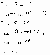
The frequency compensation components of an alternate tuning procedure (10) that has proven to work quite well is given below.
Alternate CML Tuning Parameters
 (10) (10)
This tuning approach allows for a more sensitive adjustment of the CML step response. The overshoot and rise time can be shaped by adjustment of the lead prefilter and feedback forcing lead frequencies.
3. MODEL INTEGRATION OF THE 12 PULSE D-C BRIDGE
To include the 12 pulse bridge and the CML associated with it, the complete electrical configuration must be translated into the Laplace domain. Fig's 11 and 12 present the electrical and equivalent Laplace diagrams. Fig. 12 is obtained from the following relationships between the given voltages and currents, obtained with circuit analysis techniques.
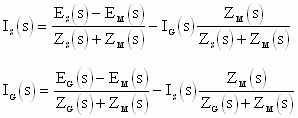
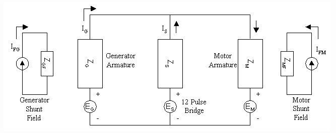
Figure 11. Electrical Diagram of MG-Set in Parallel with The 12 Pulse Bridge
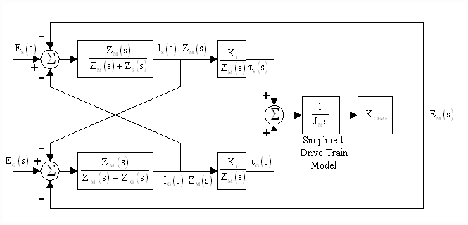
Figure 12. Laplace Equivalent of Fig. 11 (Including Motor Inertia but excluding the motor and generator shunt fields)
Ignoring the generator and motor shunt fields and the diode action of the 12 pulse bridge SCR electronics for the moment, Fig. 12 forms the basis from which a dynamic simulation may be constructed.
Individual current reference magnitudes to both the MG_Set CML and the 12 pulse bridge CML are set as a function of the CML reference from the speed loop. A fuzzy rule-based circuit senses the level and rate of change in current reference and adjusts the reference levels to the MG-Set and 12 pulse bridge CML’s. Briefly, when the reference is close to becoming negative and/or the rate of change in current is sufficiently negative large the reference to the 12 pulse bridge is reduced to zero, when the current is positive an evenly partitioned reference to both the 12 pulse bridge CML and the MG-Set CML is used. All transitions in the references are implemented in such a way that they are smooth. The 12 pulse bridge CML configuration with the MG_Set generator disconnected from the motor armature circuit and the rotor locked is presented in Fig. 13.
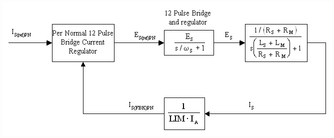
Figure 13. 12 Pulse Bridge CML With Locked Rotor
The Current loop in Fig. 13 is tuned to provide a step response that closely mirrors the step response of the MG_Set CML with which it is being coupled. The resulting equivalence in bandwidth ensures smooth load sharing and minimizes exchanges of energy between the two voltage sources.
4. DYNAMIC MODELING OF THE MG-SET CML CONTROL LOOP
A dynamic simulation of a drive section from the mill was developed to investigate the robustness of the CML control strategy for a set of worst-case plant parameter variations. The model was verified with empirical data obtained during the commissioning of the drives. The simulation was performed in the MATLAB/SIMULINK simulation environment. The structure of the simulation is given in Fig. 14.
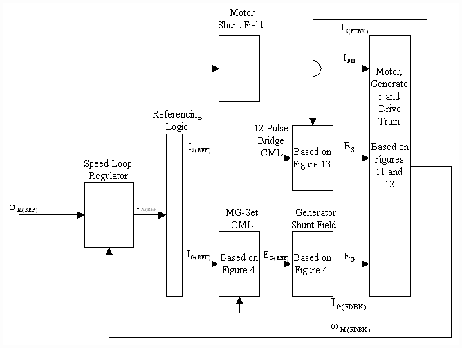
Figure 14. Dynamic Simulation Structure
The drive train model and the generator eddy current models used in the simulation were more detailed than those presented in this paper. Backlash was included in the drive train model based on the knowledge that there were significant backlash problems associated with the drive trains of the number 4 and 5 mill stands. Armature reaction effects were not included, however SCR diode action was included in the model.
To maintain armature voltage constant for speeds in the motor field range the motor field is weakened as a function of speed reference. As a consequence the reference to the motor shunt field current regulator contains no high frequency components and df/dt is negligible. While this approach may result in some variation in armature voltage during acceleration of the mill, the benefits realized by low df/dt’s in the motor field (i.e. negligible eddy currents in the motor frame) far outweigh the inconvenience of a slight variation in armature terminal voltage. This approach enables the effect of motor shunt field flux weakening to be modeled as a pure gain term in the motor torque and CEMF feedback paths, and the effects of eddy currents in the motor can effectively be ignored.
4.1 SIMULATION RESULTS
A typical stand of the Inland Steel 5 stand cold rolling mill is comprised of two 4000 [HP] motors with the armatures connected in parallel. Load sharing is accomplished with cross-coupled series fields and a slow field current trim regulator. The motors are capable of sustaining 200% rated current during mill acceleration. For the simulation the two motor armatures were lumped together. Following are the plant parameters that were also used in the simulation.
|
Simulation/Plant Parameters |
|
|
Generator Parameters: |
|
|
Armature Rated Voltage [VDC] |
700 |
|
Armature Rated Current [A] |
4600 |
|
Armature Resistance [Ohms] |
0.00319 |
|
Armature Inductance [H] |
0.000381 |
|
Field Rated Voltage [VDC] |
360 |
|
Field Rated Current [A] |
72 |
|
Field Resistance [Ohms] |
1.51 |
|
Field Inductance [H] |
3.3 |
|
12 Pulse DC Bridge Parameters: |
|
|
Terminal Voltage [VDC] |
700 |
|
Maximum Source Current [A] |
4500 |
|
Inductance [H] |
0.00012 |
|
Resistance [Ohms] |
0.046 |
|
Motor Parameters (motor armatures lumped together): |
|
|
Armature Rated Voltage [VDC] |
700 |
|
Armature Rated Current [A] |
4600 |
|
Armature Max Current [A] |
9200 |
|
Armature Resistance [Ohms] |
0.00599 |
|
Armature Inductance [H] |
0.000204 |
|
Field Rated Voltage [VDC] |
360 |
|
Field Rated Current [A] |
128 |
|
Field Resistance [Ohms] |
1.1 |
|
Field Inductance [H] |
3.42 |
|
Motor Base Speed [rpm] |
200 |
|
Motor Weak Field Speed [rpm] |
500 |
|
Motor Horse-Power [HP] |
8000 |
Tuning Parameters:
|
w C |
50 [rad/sec] |
|
w CML |
50 [rad/sec] |
|
w FML |
100 [rad/sec] |
|
w RLD |
35 [rad/sec] |
|
w RLG |
140 [rad/sec] |
|
w FLD |
25 [rad/sec] |
|
w FLG |
150 [rad/sec] |
|
Kpc |
0.11 |
For both the simulation and the on-site testing dIA/dt is limited to 20 P.U. to prevent problems with commutation in the motor and generator. To avoid exceeding this rate limit the current steps were limited to 10%, which is reasonable for CML bandwidths less than 100 [rad/sec]. Fig. 15, presents a simulated "locked rotor" CML step response from 7.5% to 17.5% rated current. The combination of FML regulator and eddy current models in the simulation produce a reasonable estimation of the non-linear dynamics of the FML. The differences between the non-linear response of Fig. 15 and the linear responses in Fig. 9 clearly demonstrate this.
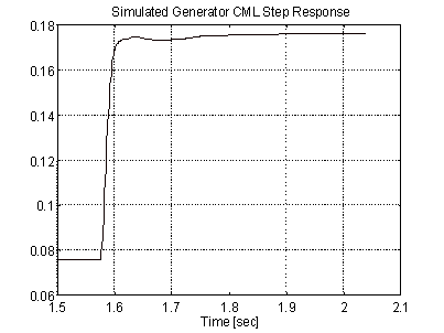
Figure 15. Simulated Generator 10% CML Step Response
Fig. 16 presents simulated 100 - 125 [rpm] speed step responses of mill stand No. 4. The Speed loop was tuned for a 12 [rad/sec] response. For both the locked rotor CML step responses and the speed step responses there was good agreement between the responses from the model and the responses obtained on-site.
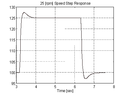
Figure 16. Simulated 25 [rpm] Speed Step Response
5. CONCLUSIONS
A Significant improvement in speed loop response in solid frame MG set mill stands can be achieved by implementing a high bandwidth armature current loop. The CML implementation differs from previous designs in that; 1) A loop is closed around generator shunt field current, 2) A combination of feedback forcing and lead pre-filtering is used to provide robustness in the MG-Set CML. The effectiveness of the design is contingent on the generator FML providing some form of compensation for eddy current effects in the generator.
References
[1] Gibson, J. E. and Tuteur F. B., "Control System Components ", McGraw Hill, 1958.
[2] Smith, E. P., "Transient Characteristics of D-C Metal-Rolling Motors and Generators ", AIEE Transactions, pp 326-340, January 1957.
[3] Dunaevsky, S. I., "Effect of Eddy Currents on Magnetic Flux" , Elektrichestvo (in Russian), Feb. 1951. pp. 55-63.
[4] Clark, R. N., "Another Reason to Eschew Pole Zero Cancellation" , IEEE Control Systems Magazine, April. 1988. pp. 87-88.
[5] Chen, C. T., "Control System Design" Pond Woods Press, 1987
[6] Fapiano, D. J., R. M. Sills"Electric Drive Systems for Rod and Bar Mills" , Iron and Steel Engineer Year Book , 1973. pp. 514-520.
|