PAPER No. 7
Applying Drive Specifications to Systems Applications:
Part I Speed Regulation
1999 IEEE IAS Annual Meeting
Brian Thomas Boulter
Applied Industrial Control Solutions LLC
4597 E Sprague Rd.
Independence, OH, USA 44131
© ApICS ® LLC 2000
Abstract- This paper provides guidelines for the useful interpretation of AC/DC drive speed performance specifications from a drive system’s application perspective..
I. Introduction
The technical climate in today’s drive systems business markets has been inundated by drive vendor claims of ever improving drive performance specifications. The objective of this report is to bring these performance specifications into technical focus, and provide the reader with a basis for correctly interpreting them from a systems/applications perspective. Space constraints only allow for a discussion of speed specifications. Future papers will address performance issues associated with cascaded and "parallel", position, tension, and torque regulation schemes.
It is hoped that the reader will walk away from this presentation with the tools required to sift through a given drive’s speed performance specifications, and glean from them those points that are truly of importance to the application in question.
To summarize, most of the time the chief performance limiting mechanism in a system is not the responsiveness of the drive, but the physics of the application and/or the system architecture.
A. Paper Overview
The paper is divided into four sections. The first section is composed of this introduction, the second section defines a set of useful terms, the third section defines the most important drive specifications with respect to speed, and methods of determining these criteria for a given drive. The report conclusions are presented in the fourth section.
II. Some useful definitions
Three definitions that prove useful in understanding drive system speed performance criteria are, control loop bandwidth, per-normal Inertia, and noise sensitivity
Control Loop Bandwidth (Fig. 1): Bandwidth is defined as the frequency at which the closed loop response of the controlled variable is attenuated 3 [db] from the set point. It is also approximated as the point at which the open loop gain of the system is unity and is called the "crossover" frequency. The Bode plot graphically represents the magnitude and phase of the ratio of output to input over a range of input frequencies. Therefore, unity gain of the system at the crossover frequency implies that, at that frequency, the output and the input of the open-loop system are equal in magnitude. And at all frequencies below this frequency , the closed loop has unity gain.
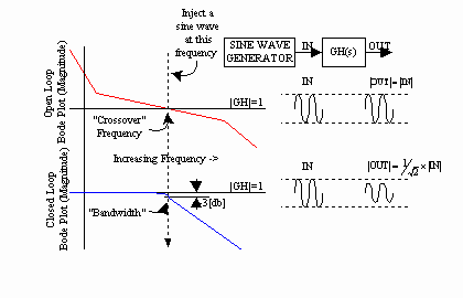
Fig. 1. Bandwidth Definition
Per-Normal Inertia (Fig. 2): Per-normal reflected inertia [sec] is the time in seconds that it takes to accelerate the motor and load inertia from zero speed to motor base speed (Sb) with motor rated torque (tRated) and the given reflected inertia (J).
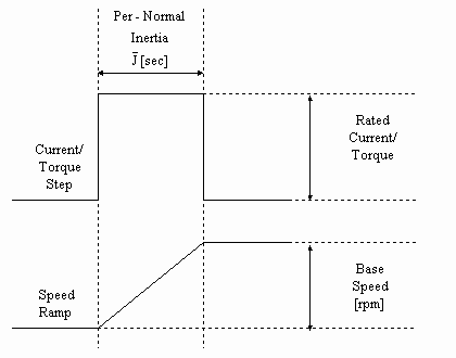
Fig. 2 Per-Normal Inertia [sec]
Imperial units: 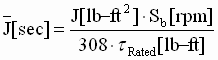 (1) (1)
SI units: 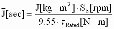 (2) (2)
Noise Sensitivity (Fig 3.): The concept of noise sensitivity is important when the gain of a control loop is taken into account. This can be easily demonstrated: Assume an application has a speed loop resolution of 1 part in 10,000, and a torque loop resolution of 1 part in 10,000, and the speed feedback is corrupted by 10 counts of system noise. In addition, make the assumption that the proportional gain of the controller has been increased to 1,000, to get more "response" out of the drive. When amplified by the proportional controller gain, the noise will produce 10,000 counts of torque reference noise. Clearly, injecting noise with amplitude equal to the maximum torque capability of the drive will adversely affect the drive train integrity. This noise typically comes from uncontrolled mechanical and electrical sources, such as machine vibration, encoder shaft vibration, and electrical emi. Noise in control systems cannot be avoided, and will limit the maximum possible gain of any control loop. The loop gain must be constrained in such a way that an optimum trade-off between gain/bandwidth and the ability of the system to tolerate noise amplification in the controller is achieved. Frequency compensation schemes can be employed to reduce the sensitivity of the controller to noise amplification.
There are many ways of defining the noise content of a signal. However, to avoid complexity, define per-normal system noise as the ratio of the [rms] noise content found on the feedback signal, to the feedback peak-to-peak maximum value. While this approach is crude, it is an adequate description for use in industrial control systems.
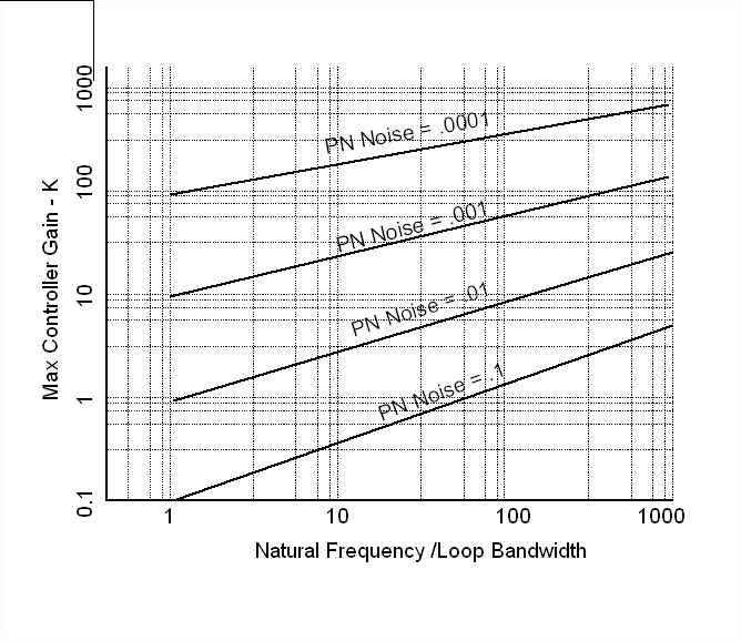
Fig. 3 Per-Normal Noise / Controller Gain Limitation
A graphical representation of noise sensitivity is given above in Fig. 3. In this graph a family of curves is used to define the maximum proportional controller gain for a given loop, as a function of the ratio of the dominant (lowest) system natural frequency to the controller bandwidth, and per-normal system noise. Depending on system natural frequency and the amount of noise in the system, there may exist significant differences in maximum possible controller gains. Each application will be different.
To use this graph the user should have some idea of the system natural frequencies, and the expected loop bandwidths. Note that not all systems are second order, and more than one system natural frequency might exist. If this is the case, choose the lowest (dominant) natural frequency.
A good example of the application of this constraint on loop gain is a drive train with a very low torsional frequency and significant backlash. Such a system will not be able to withstand much noise amplification in shaft torque. Noise is composed of a spectrum of excitation frequencies, some of which will inject energy at the torsional natural frequency of the drive train. If the energy contained in the excitation is high enough to exceed an application dependant threshold, the energy exchanged between the inertia and the drive shaft will grow in magnitude. Determining the noise amplification/energy threshold point at which a system becomes unstable is the subject of much research in the area of non-linear controls, and chaotic system behavior. However, from an industrial control systems perspective, the understanding that a threshold point exists and that exceeding it causes instability is adequate.
How to measure the noise content of your application? Run the drive as a speed regulator, average the current reference with a running average filter, then force the current reference to the averaged value. Measure the speed feedback through a scope with the AC setting (to remove any bias, or drift in the measurement), and then divide the measured noise voltage [rms] by the maximum peak-to-peak voltage. This will yield the PN-noise value.
- Interpreting Drive Performance Specifications
Speed performance specifications provided by most vendors usually deal with the definition of an absolute maximum drive performance capability. These specifications assume ideal operating conditions (i.e. PN Noise and a PN Inertia that is low enough, and a natural frequency that is high enough, to allow the loop gain to be increased to a value that yields the specified bandwidth).
The following two specification types clearly define the performance of a speed loop with any drive:
Static: Defines the effective resolution.
Dynamic (Bandwidth): Defines the dynamic capability.
A) Static accuracy: The specification that defines the effective resolution of the speed loop. It is generally specified as a percentage of speed maximum. There are three types of speed feedback devices used on almost all speed feedback applications; the resolver, the pulse tachometer, and the analog tachometer.
In applications that utilize resolvers, the governing factor in determining the static accuracy of the speed loop is the electrical error of the resolver. In pulse tachometer applications the accuracy of the speed feedback will depend on the number of pulses per revolution of the feedback device, and the drive vendor’s proprietary pulse feedback to speed estimation mapping algorithm. Some of these algorithms employ Kalman Filtering techniques, and other predictive approaches that greatly increase the accuracy of the speed feedback estimation, without the need to increase the number of pulses per revolution. In Analog tachometer applications the accuracy is usually limited by electrical and mechanical characteristics of the tachometer and the amplifier electronics. In resolver and pulse tachometer applications, the effect of electrical noise is minimized, however in analog tachometer applications, electrical noise becomes an important issue.
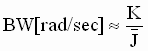
B) Dynamic Accuracy: The loop bandwidth of a speed loop, closed with a PI controller, can be defined using control system analysis techniques, with the following equation:
Let:
BW = Loop bandwidth [rad/sec]
K = Loop gain (i.e. the normalized gain of the control loop)
 = Per-normal (PN) reflected inertia [sec] (Fig. 2) = Per-normal (PN) reflected inertia [sec] (Fig. 2)
 (3) (3)
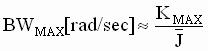
This states that the bandwidth is equal to the total controller gain divided by the PN Inertia. Based on the above discussion about noise sensitivity, it is clear that ALL control systems will be gain limited, depending on how much noise is in the system, and on the ratio of the natural frequency to the desired bandwidth. Therefore, the bandwidth will be limited to:
 (4) (4)
Where KMAX is obtained using Figure 3.
To produce the highest possible test speed loop bandwidth for a given drive, the drive vendor will conduct the speed loop performance test using an inertia and system noise that is low enough, and a test set-up torsional frequency that is high enough, so that the only remaining limitations to speed loop bandwidth are the sample rate of the speed loop, and/or the bandwidth of the current/torque minor loop. Under these ideal test conditions, the performance of the drive itself is the only factor limiting the performance of the speed loop.
As a good rule of thumb, to maintain phase margin and stability in the speed loop, its bandwidth must be limited to 1/3rd to 1/5th the bandwidth of the current/torque loop, and/or p times 1/3rd the inverse of the speed loop sample time TS [sec], whichever is lower:
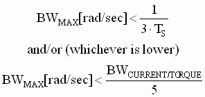 (5) (5)
Based on the above discussion, the maximum speed loop bandwidth of ANY drive system in a given application can be found by using the following procedure:
Step 1: Identify the maximum possible loop gain (KMAX) using Fig. 3, and your best guess about the quantity of system noise in the control loop, the expected bandwidth of the speed loop, and the natural frequency of the system.
Step 2: Identify the per-normal inertia ( ) of the system using a test (Fig. 2) or calculations (1,2). ) of the system using a test (Fig. 2) or calculations (1,2).
Step 3: Identify the maximum bandwidth of the system independent of the drive technology used, using (4).
Step 4: Check to verify that the BWMAX computed in Step 3 is within the constraints imposed by the drive technology used (5). If not, constrain the value of BWMAX to the imposed constraints.
Step 5: If the constrained speed loop bandwidth is less than the desired value used in step 1, take the final value of BWMAX from Step 4 and re-iterate from Step 1 to Step 4. If the initial speed loop bandwidth guess was way-off, you may have to repeat this several times.
Following the above steps yields a fairly accurate estimate of the maximum possible speed loop bandwidth for a given application. Upon using this approach, it quickly becomes clear that in almost all systems applications the limiting factors governing speed loop performance are the maximum loop gain (i.e. the noise sensitivity, and system natural frequency) and system inertia. Only on a rare occasion does the drive technology used adversely impact speed loop performance. In some applications, torque loop bandwidth is required when novel feed-forward control strategies are deployed. For example, novel torsional resonance, and friction compensation schemes, and the rare application that is sensitive to error in a ramped torque reference ([1],[2],[3]). These applications DO require bandwidth in the torque minor loop, but do not necessarily require bandwidth in the speed loop. Following are some examples that illustrate the above points:
Ex. 1) Hard disk drive:
|
Inertia |
1e-6[kg-m^2] |
Reflected Inertia |
|
Sb |
8000 [rpm] |
Motor base speed |
|
(tRated) |
0.08 [N-m] |
Rated Motor torque |
|
PN Noise |
0.0001 |
Per normal noise |
|
w n |
6000 [rad/sec] |
System natural frequency |
|
BWTorque |
3000 [rad/sec] |
Torque loop bandwidth |
|
Ts |
0.1 [msec] |
Speed loop sample time |
Step 1: KMAX = 100 (assume wn/ wBW = 10)
Step 2:  = 0.01 [sec] = 0.01 [sec]
Step 3: Theoretical BWMAX = 10,000 [rad/sec]
Step 4: Constrained BWMAX = 600 [rad/sec] (1/5th BWTorque)
Step 5: Final BWMAX = 600 [rad/sec] (i.e. 95 [Hz])
In this application the performance of the speed loop was constrained by the drive technology (i.e. final BWMAX constrained by the torque loop bandwidth, was much lower than the theoretical BWMAX), clearly a more responsive torque loop, in this application, will result in a more responsive speed loop.
Ex. 2) Steel Strip Process Line Bridle Roll:
|
Inertia |
40 [lb-ft^2] |
Reflected Inertia |
|
Sb |
1750 [rpm] |
Motor base speed |
|
(tRated) |
150 [ft lb] |
Rated Motor torque |
|
PN Noise |
0.001 |
Per normal noise |
|
w n |
300 [rad/sec] |
System natural frequency |
|
BWTorque |
3000 [rad/sec] |
Torque loop bandwidth |
|
Ts |
5 [msec] |
Speed loop sample time |
Step 1: KMAX = 20 (assume wn/ wBW = 20)
Step 2: = 1.5 [sec]
Step 3: Theoretical BWMAX = 13 [rad/sec]
Step 4: Constrained BWMAX= 66 [rad/sec] (1/3rd 1/Ts)
Step 5: Final BWMAX = 15 [rad/sec] (i.e. 2.4 [Hz])
In this application the performance of the speed loop was constrained by the system inertia, and the noise sensitivity of the system. Clearly, in this case a faster torque loop would provide no significant performance benefits.
Ex. 3) Steel Hot Rolling Mill Stand drive:
|
Inertia |
1000 [lb-ft^2] |
Reflected Inertia |
|
Sb |
450 [rpm] |
Motor base speed |
|
(tRated) |
3000 [ft lb] |
Rated Motor torque |
|
PN Noise |
0.0005 |
Per normal noise |
|
w n |
600 [rad/sec] |
System natural frequency |
|
BWTorque |
3000 [rad/sec] |
Torque loop bandwidth |
|
Ts |
10 [msec] |
Speed loop sample time |
Step 1: KMAX = 30 (assume wn/ wBW = 20)
Step 2: = 0.5 [sec]
Step 3: Theoretical BWMAX = 60 [rad/sec]
Step 4: Constrained BWMAX = 33 [rad/sec] (1/3rd 1/Ts)
Step 5: Final BWMAX = 33 [rad/sec] (i.e. 5.2 [Hz])
In this application the performance of the speed loop was constrained by the sample rate of the speed loop. In this case, as in the case above, a faster torque loop would have provided no performance benefits, however increasing the sample rate of the speed loop would have resulted in an improvement in the speed loop bandwidth.
Ex. 4) Paper Machine Yankee Dryer:
|
Inertia |
34,000 [lb-ft^2] |
Reflected Inertia |
|
Sb |
450 [rpm] |
Motor base speed |
|
(tRated) |
1000 [ft lb] |
Rated Motor torque |
|
PN Noise |
0.001 |
Per normal noise |
|
w n |
50 [rad/sec] |
System natural frequency |
|
BWTorque |
3000 [rad/sec] |
Torque loop bandwidth |
|
Ts |
20 [msec] |
Speed loop sample time |
Step 1: KMAX = 50 (assume wn/ wBW = 50)
Step 2: = 50 [sec]
Step 3: Theoretical BWMAX = 1 [rad/sec]
Step 4: Constrained BWMAX = 16 [rad/sec] (1/3rd 1/Ts)
Step 5: Final BWMAX = 1 [rad/sec] (i.e. 0.15 [Hz])
In this application the performance of the speed loop was severely constrained by the system inertia, and the noise sensitivity of the system. A faster torque loop and/or a faster sampled speed loop would provide no performance benefits to the speed loop.
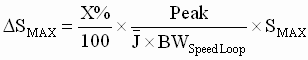
- Speed Loop Load Shock Recovery Time:
Another useful measure of speed loop performance is load shock recovery time. This is the time it takes the speed loop to return to a given percentage of maximum speed, after a load shock equivalent to a given percentage of rated torque is applied to the motor shaft. This specification can also be expressed in terms of speed loop bandwidth (BW), and PN inertia (), as shown in Fig. 4 below. Fig. 4 is only applicable to speed loops with the ratio of the PI lead frequency to speed loop bandwidth is equal to 1/5. (Note: PI lead frequency = the ratio of Integral to proportional gains, i.e. wld = Ki/Kp)
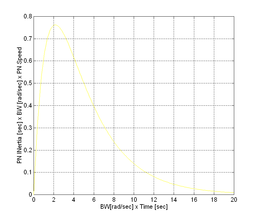
Fig. 4 Load Shock Recovery Time
The following procedure can be used, with Fig. 4, to calculate the time to recover to a speed of DS after a DSMAX speed deviation caused by an X% of rated load shock:
Step 1: Determine the reflected PN Inertia [sec] of the system using (1,2) or a test.
Step 2: Determine the bandwidth of the speed loop (BWSpeed Loop) using the procedure defined in the previous section.
Step 3: Determine the maximum speed deviation (DSMAX) for the specified load shock (6)
 (6) (6)
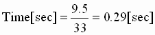
Step 4: Determine the Time to recover from the load shock:
- Let
 , Where DS is the recovery speed. , Where DS is the recovery speed.
- Calculate the Y-Axis lookup value using (7)
 (7) (7)
- Calculate the time it takes to recover using (8)
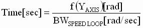 (8) (8)
Note: the calculation of DSMAX is not required for the computation of the recovery time, it is provided as an additional measure. Some applications specify the maximum speed dip for a given load shock.
Following is an example of this procedure:
Ex. 1) Steel Hot Rolling Mill Stand drive:
|
Inertia |
1000 [lb-ft^2] |
Reflected Inertia |
|
Sb |
450 [rpm] |
Motor base speed |
|
(tRated) |
3000 [ft lb] |
Rated Motor torque |
|
PN Noise |
0.0005 |
Per normal noise |
|
w n |
600 [rad/sec] |
System natural frequency |
|
BWTorque |
3000 [rad/sec] |
Torque loop bandwidth |
|
Ts |
10 [msec] |
Speed loop sample time |
|
X% |
100% |
torque load shock % |
|
D S |
4.5 [rpm] |
Recovery speed [rpm] |
Step 1: = 0.5 [sec]
Step 2: BWMAX = 33 [rad/sec]
Step 3:
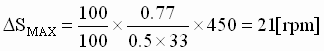
Step 4: DSPN = 4.5/450 = 1%
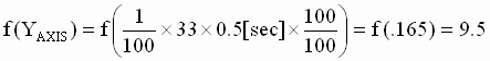
Therefore:
A family of curves for a set of ratios of PI lead frequencies to BWMAX is presented in Fig. 5. This figure is used in the same way as that described in the procedure above, with the exception that the appropriate curve for a given PI lead to BW ratio be used.
Note that (6). Must be modified as follows:
 (7) (7)
Where ‘Peak’ is the peak value of the appropriate Curve in Fig. 5.
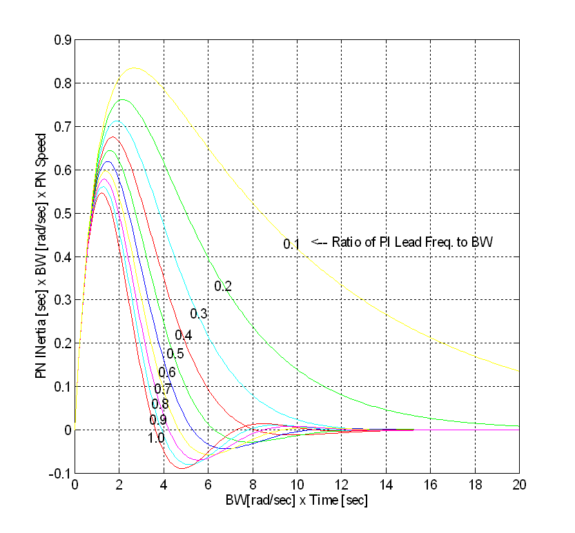
Fig. 5 Speed Loop Load Shock Recovery Time
(For Ratios of PI lead Frequency to BW Varying From 0.1 to 1.0 in steps of 0.1)
IV. Conclusions
The four earlier examples illustrate that there are both physical, and technology dependant factors that limit the responsiveness of a speed regulator. Briefly, in systems where there are high inertia, and/or noise sensitivity factors limiting the bandwidth (Fig. 3) the use of a "more responsive" drive will provide no additional benefit. In fact experience has shown that in some of these applications, "low technology" MG sets perform every bit as well (some would say better) than their high bandwidth static drive counterparts.
In applications where the inertia is low enough, and the system natural frequency high enough. The loop gain may be increased to a point where either the sampling time of the speed loop, and/or the bandwidth of the torque loop, limit the responsiveness of the speed loop. The use of faster sampling and/or a "more responsive" AC or DC static drive in these applications will provide measurable benefits.
Some applications require high torque loop bandwidths to fully utilize novel torsional and/or friction compensation schemes. In these applications the need for bandwidth does not arise from a need to improve speed regulation, but rather to compensate for a debilitory physical property associated with the mechanics of the machinery. In other applications terminal voltage slewing can impact the performance of a drive in a given application, (e.g. screw down motors on gauge control systems.) These applications require a unique torque regulator structure, that has zero error to a torque ramp. These issues are discussed at length in [1,2,3].
In the interest of fairness, all drive supply vendors should employ measures of drive performance that allow the purchaser of the drive to compare "apples to apples". The author recomends using the approach shown in this paper, where: 1) Static performance measures are in terms of percent deviation from setpoint [%], and 2) Dynamic performance measures are expressed in terms of bandwidth [rad/sec] (frequency domain method). As an alternate dynamic performance measure, the load shock recovery time (time domain method) may be used.
The conditions under which the expected dynamic response can be achieved should be CLEARLY expressed (i.e. the per-normal inertia, the system noise requirements, and the torsional natural frequency).
Alternately, the drive purchaser may themselves employ the techniques described in this paper to determine if the drive has the response required to meet the requirements of his/her particular application. Employing these analytical techniques will greatly improve the ability of the drive purchaser to make intelligent application-specific decisions about his/her drive speed performance requirements.
References
[1] Wilkie R.J., Parkes L.S., "A User’s Experience with the Present Generation of Digitally Controlled DC Drive Systems" , unpublished, Internal BHP Engineering Publication, BHP Steel, Port Kembla, NSW Australia.
[2] Godfrey N. R., "A fundamental Approach to the Design of Regulating Systems for DC variable Speed Drives". unpublished, Internal BHP Engineering Publication, BHP Steel, Port Kembla, NSW Australia.
[3] Godfrey N. R., Parkes L.S., Wilkie, R.J., "High Performance Speed Regulation of Rolling Mill DC Drives Connected to a Common Voltage Bus". Proceeding of the 4th Conference on Control Engineering, IE Australia, Gold Coast, August 1st – 3rd 1990.
| 