Brian T. Boulter
This report details the modeling, simulation and resulting control scheme and mechanical configuration recommendations for a coating section installed by a third party printing OEM.
This engineering report describes the modeling and simulation of an in-line coating section installed by a third part printing equipment manufacturer at an installation.
An adequately detailed model of the coater was developed. The purpose of the modeling and investigation was to observe the effect of backlash on the observed registration error in the coater, with the existing control scheme. In addition, several alternative control schemes were to be investigated, and the results presented in the following SR.
The report is divided into four sections. The first chapter defines a set of useful terms, and the governing first principal equations; the second describes the simulation structure. The third chapter presents the conclusions, and finally the fourth chapter presents a set of recommendations.
The equations describing the dynamics of this type of system have been described in detail in the engineering course "Advanced Dynamic Simulation". The following descriptions are only brief and are not intended to describe every detail of the simulation. The derivation of all the equations used to describe the dynamics of the described system, can be also be found in the same course material.
System Description:
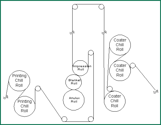
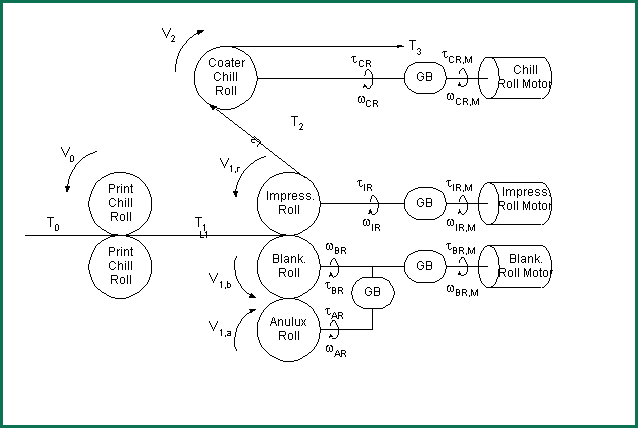
The system that is modeled in the simulation is shown in Figure 1-1. The printing process chill section is modeled as an ideal speed/tension source. The exit of the coater chill section is modeled as an ideal tension sink. A simplified diagram of the system is presented in Figure 1-2. The simplified system representation is described with the same nomenclature that is used in the first principal equations.
All radii, inertias, gear ratios, and other physical properties relating to the modeled plant used in the simulation are subscripted with the following symbols:
|
Impression Roll |
IR |
Impression Roll Motor |
IR,M |
|
Blanket Roll |
BR |
Blanket Roll Motor |
BR,M |
|
Anulux Roll |
AR |
|
|
|
Chill Roll |
CR |
Chill Roll Motor |
CR,M |

Figure 1-1. Coater System

Figure 1-2. Simplified Coater System Representation
The web spans in the process are computed as the lengths of free web spanned in the section. The inertias used in the simulation were calculated based on a combination of information supplied by the OEM, and a-priori knowledge of typical inertias for these types of systems. All information pertaining to gear ratios, diameters, radii, and free span lengths were supplied by the OEM.
Shaft spring constants were computed based on a-priori knowledge of typical natural frequencies for these types of mechanical systems. Similarly, guesses were made with respect to gear-box damping of higher order resonant modes, and the properties of material damping associated with the conveyance of cardboard material through this type of processing equipment. The values typically used for hard Kraft paper were used in this case.
The investigation of the effect of backlash in the gear-box was accomplished with best guesses about the typical backlash found in the gear-boxes on-site.
CHAPTER 4
OBSERVATIONS AND RECOMMENDATIONS
Observations
The plots of all the sets shown in Chapter 3, indicate that little relative improvement was made when any of the typical control approaches to compensating for gear-backlash were implemented. It is the authorís opinion, that the main reason for the ineffectiveness of these control schemes is due to the surface speed jitter in the impression roll.
Given that the impression roll inertia, and the reflected inertia of the impression roll motor at the strip are of the same order of magnitude, and relatively low, the motor speed regulator will not have any trouble tracking a speed reference, even in the presence of gear-backlash. This is so, despite any large changes that may occur in the surface speed of the impression roll. Evidence of this was obtained in the simulation results (not presented), which showed that the motor speed was significantly less noisy than the surface speed of the impression roll.
On the blanket roll however, the reflected motor inertia, at the blanket roll surface, was an order of magnitude smaller than the blanket roll. This indicates that backlash will be a significant problem in terms of tuning the speed regulator for tracking a speed reference, however, a hidden benefit is that the surface speed of the blanket roll will not deviate as much as the impression roll, given the same magnitude of a given load disturbance. In fact the blanket roll gears should stay fairly well loaded on one side of the gear surface. The same cannot be said for the impression roll. It is likely that the impression roll is bouncing in and out of a loaded gear condition, as each impression is made, and as any load disturbances from the process are injected into the coupled system.
It is also highly likely that the exit chill roll of the printing section (and in all likelihood the entire chill section) introduce some web surface speed deviations into the impression roll section of the coater through the coupled web material. These disturbances will tend to cause the impression roll to break in and out of an oscillatory unstable condition, while at the same time the blanket roll may remain fairly well behaved. This phenomena is exaggerated by the fact that the blanket roll surface is loosely coupled to the web through an impression and a thin layer of coating material, while the impression roll is tightly coupled to the web, through a set tension, and a large wrap angle.
Several drive regulator configuration options could help this alleviate the sensitivity of the impression roll to backlash, but these would only assist in making the drive speed feedback look better, they will not in any way help with the effect of a attenuating deviations in the impression roll surface speed as long as there is backlash in the impression roll gear-train.
To summarize the observations made from the simulations:
- The existence of backlash in this mechanical configuration is extremely depilatory to the accuracy of the coating registration.
- The system is most sensitive to the existence of backlash in the drive train of the impression roll.
- Small improvements in system registration can be made with modifications to the existing control scheme.
- Existence of tension deviations in the chill section of the printing section will cause problems in the registration of the coating section.
Recommendations
The following recommendations are based on observations made during the simulation, and discussions with several systems engineers at the drive vendor:
- If the coupling between the printing process chill section and the impression roll is tight, and the exit speed of the mechanical line shafted printing section is stiff, the use of a speed regulator on the impression roll will lead to the interactions that were described earlier, and cause the impression roll surface speed to bounce around. To alleviate the possibility for this type of interaction, we recommend configuring the impression roll as a torque regulator, or at the least, a soft speed regulator with a significant amount of current compounding.
- The simulations show clearly that the existence of backlash in all the drive trains severely impacts the registration between the blanket roll and the impression roll. To alleviate this as a possible source of contention between the desire to regulate good surface speed, and compensate for gear backlash, the mechanical configuration should be looked at, with the aim in mind of removing backlash from the drive-trains. This is especially true for the impression roll drive-train.
- Given that the above actions result in a substantial improvement in the consistency of registration, the registration loop should be enabled and tuned.
This concludes the engineering report.
