ABSTRACT
This report details the modeling, simulation and resulting control scheme configuration recommendations for a proposed automotive dynamometer transmission test stand. The test stand is innovative in that electric motors and drives are being used to emulate both the engine and vehicle inertias, and the road/vehicle loading of the transmission.
The control strategy that is to be used in the final design is also presented. Results of a simulation from an adequately detailed model of the transmission, drive train including the test stand, and transmission torsional dynamics, are also presented.
INTRODUCTION
Scope
This report presents a detailed description of the modeling, simulation and resulting dynamometer control scheme configuration development and recommendations for a proposed automotive transmission test stand.
Objective
An adequately detailed model of the proposed test stand was developed. The purpose of the modeling and investigation was to observe the effectiveness of the described dynamometer control scheme during transmission gear changes.
Specifically, the effectiveness of the dynamometer engine inertia emulation algorithm and the road load/vehicle inertia emulation algorithm, during gear changes, for a set of loaded/unloaded grade/no-grade operating conditions was to be investigated. The methodologies used in the simulation were based on algorithms and modeling approaches found in [2,5,6,7].
A simple engine model and a road-load model is also presented. A method that is to be used in the final implementation of both the engine model and the described control strategy is also described. The results of the investigations are presented in this SR.
Report Overview
The report is divided into four sections. The first chapter defines a set of useful terms, and the governing first principal equations; the second describes the simulation structure. The third chapter presents the results from simulations of the system, and finally the fourth chapter contains a set of concluding remarks.
CHAPTER 1
FIRST PRINCIPAL EQUATIONS
Introduction
The equations describing the dynamics of the sub-systems that comprise a typical dynamometer transmission test stand have been described in detail in the ApICS systems engineering course 10 "Advanced Dynamic Simulation" [2] and several research sources [5,6,7]. The friction models used were obtained from [2,3,4]. The descriptions of the describing equations used in this simulation are only brief and are not intended to be rigorous. The derivation of the describing equations used in this report can be found in the same reference material.
The one exception is the modeling technique used to provide the simulation with an adequately accurate representation of the transmission dynamics during a gear-shift in the test stand. A more detailed explanation of the methodology used is presented.
System Description:
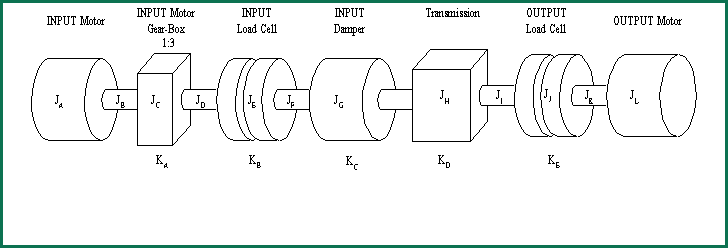
The test-stand specifications are described in detail in [1]. A mechanical one-line diagram of the test stand is shown in Figures 1 and 2. The inertias (Ji) and system spring energy storage elements (Ki) are shown, along with the descriptive names for each of the major components.

Figure 1-1. Test Stand Mechanical Configuration
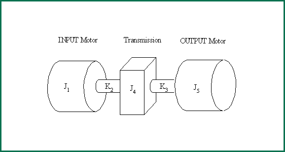
Unnecessary detail in the above model can be removed and a simpler model will result. The simplification of the model will remove high frequency resonant modes that are not of interest in the simulation. These modes result from the very stiff springs and low inertias of the shafts that couple the system components together. Figure 1-2 shows the simplified model.

Figure 1-2. Simplified Test Stand Mechanical Configuration
CHAPTER 4
CONCLUSIONS AND RECOMMENDATIONS
Conclusions
The following conclusions were drawn from the exercise of modeling, and simulating the proposed mechanical and electrical system.
- The engine model exhibits instability when required to regulate a given speed [rpm] with a relatively low torque.
- The tuning of the governor in the engine model may require some adjustment during start-up. To obtain the best speed regulation in the simulation, the Proportional term of the governor regulator was changed from 0.0009616 to 0.003 in the simulation. The derivative gains of the regulator and the D speed feed-back fuel-rate feed-forward regulator were not changed.
- The engine model will stall, if a given test set-up requires performance outside the particular engine modelís torque-speed envelope.
- The resonance compensation circuit was sufficiently robust to enable the prescribed tuning for an empty vehicle to work adequately with a full vehicle. If there are significant changes in the simulated vehicle mass, resulting in a significant change in the dominant natural frequency of the closed-loop test stand set-up, set-up dependant tuning parameters for the RES-COMP filter will be required.
- The noise sensitivity of the derivative of the speed feedback was significantly enhanced by deploying the rate controlled ramp function on the speed derivative.
- The dynamometer inertia emulation algorithm on the transmission OUTPUT stand performed very well.
- The dynamometer engine inertia emulation algorithm on the transmission INPUT stand also performed well during reasonable rate changes in speed. The speed deviations caused by the torque spikes on the INPUT stand that occurred when the simulated transmission gears re-engaged, were also compensated for. However, the response of the inertia emulation circuit was not fast enough to completely isolate the input shaft of the transmission from the higher reflected electric motor inertia during these changes. It is expected that the actual shaft torque excursions during transmission gear-changes will be somewhat less than the observed deviations in the simulation, resulting in better inertia emulation than that which was observed in the simulation.
- The road-load model produced very convincing road-load conditions. The equations provided enough adjustments to create any desired loading conditions on the transmission.
Recommendations
The following recommendations are the result of taking into consideration the above conclusions, and discussions with several Systems Engineers at RA.
- The simplified engine model used in the simulation can easily be implemented in an appropriate DCS processor with a combination of functions and/or high level language code. A single separate processor should be scheduled to perform all the engine modeling tasks.
- The INPUT and OUTPUT regulators should be scheduled in a processor that is in the same rack as the processor containing the tasks with the engine model.
- A recipe based level 2 set-up interface will be required. The recipe should download engine model data, INPUT and OUTPUT stand tuning and calibration data, and the appropriate sequencing to perform the desired road-load emulation for a given test.
- Care should be taken to ensure that the parameters of the transmission tests that are in the recipe do not require the engine model used in the tests to perform outside the design speed-torque envelope of the engine that is being emulated. This is to avoid stalling the test set-up.
- Care should also be taken to ensure that the transmission test set-ups are devised to regulate a given speed with sufficiently high torque. This is to avoid the governor regulator instability that can be seen in sets (1.2,3) for example.
This concludes the engineering report.
