APPLIED INDUSTRIAL CONTROL SOLUTIONS
ApICS LLC.
Winder Tension Control Simulation
&
A Robust Winder Tension Control Algorithm
B. T. BOULTER
© ApICS ® LLC 2000
ABSTRACT
This engineering study, satisfies the requirements prescribed in Systems Engineering Proposal "CLUTCH TENSION CONTROL SIMULATION AND DEVELOPMENT OF A ROBUST TENSION CONTROL ALGORITHM" Brief sets of results that reflect the expected system performance are provided. Included is a brief description of the simulation sub-systems. The simulation description is meant to provide the user with the information required to perform "what-if" scenarios using the simulation.
A detailed description of the control algorithm and all difference equations used in the simulation are also described.
INTRODUCTION
Scope
The scope of this document is limited to a brief description of the first principal equations describing the system, providing an overview of the simulation and the control structure sub-systems, and providing a detailed description of the control algorithm, including all necessary difference equations.
Results
Brief sets of results that provide insight into the expected behavior of the system with varying system configurations are included.
For each presented result, the following variables are plotted:
- Web Tensions [lb]
- Backstand/Winder torque [lb ft]
- Line speed [ft/min]
- Roll Diameter [in], and Inertia [lb ft2]
The investigations include: the effect of roll diameter on gain adaptation response time, demonstration of stable response over the entire roll build-up/wind-down. Demonstration of stable operation over a wide range of material thicknesses and elasticities.
A procedure for starting up the regulator is described, along with necessary sequencing issues that must be implemented for the regulator to operate in a safe manner.
The study concludes with some pertinent observations, and conclusions/recommendations.
CHAPTER 1
PLANT FIRST PRINCIPAL EQUATIONS
OVERVIEW
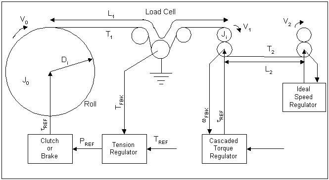
Figure 1. describes the system under study. Equations (1.1) through (1.8) describe the system shown in figure 1, with the inclusion of non-linear relationships between state variables that are not obvious from the figure.

Figure 1. System Diagram
The ideal speed regulator provides the exit velocity for the second web span, a cascaded torque regulator (i.e. a torque regulator that is cascaded around a speed regulator) is included to dampen the dynamics between the stiff speed source and the winder/backstand dancer zone.
Tension Regulator
The Tension Regulator description is protected by an IP agreemenet. It does contain an adaptive frequency based adaptation algorithm. The following discussion explains the need for this approach:
The Need for Frequency Adaptation
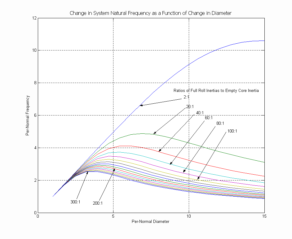
In Figures 7.b & 7.c below, plots graphing the change in the normalized (i.e. empty core natural frequency = 1 [rad/sec]) dominant system natural frequency as a function of the variation in normalized roll diameter (i.e. empty core diameter = 1) is presented. The "shape" of this variation in natural frequency as a function of diameter depends on the ratio of the full roll inertia to the empty core inertia. In Figure 7a, a family of curves is shown for a Diameter ratio of 15:1 . In Figure 7b, a family of curves is shown for a Diameter ratio of 8:1. For both the graphs, the smallest inertia ratio is 2 :1, the largest is 300 : 1. From these figures it can be seen that to properly set-up the regulator, the right "mapping" of the natural frequency as a function of the estimated per-normal diameter must be identified. This implies that the approximate ratio of full roll to empty core inertia must be entered, and based on this, the proper mapping identified. The following equations are used to identify the normalized natural frequency.
Per-normal Diameter:
 ; ;  ; ;  (1.13) (1.13)
 ; ;  ; ;  ; ;  (1.14) (1.14)
Per-normal Natural Frequency (unitless):
 ; ; (1.15a) (1.15a)
 ; (1.15b) ; (1.15b)
Where wi is the application natural frequency in units consistent with wEC

Figure 7b. Natural Frequency Vs Diameter (15:1 Diameter Ratio)
CHAPTER 2
SIMULATION STRUCTURE
Overview
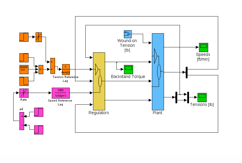
The simulation is composed of two main sub-systems: The controller sub-system (yellow block) and the plant sub-system (blue block) as shown in Figure 9. Also included are references for line speed (magenta blocks) , wound-on tension, and tension reference (orange blocks). Scopes used for monitoring, and data storage blocks are represented by green blocks.

Figure 9. Simulation Main Block Diagram
Reference Generation
CHAPTER 4
SEQUENCING ISSUES & START-UP PROCEDURES
The contents of this Chapter PROPROETARY
BIBLIOGRAPHY
[1] Hess, D.P., Soom, A. "Friction at a Lubricated Line Contact Operating at Oscillating Sliding Velocities" Journal of Tribology Transactions of the ASME Vol 112, pp 147-152, 1992.
[2] Majd, V.J.. Simaan M. A., "A Continuous Friction Model For Servo Systems With Stiction", Proceedings of the 4th I.E.E.E. Conference on Control Applications, Albany NY. 1996
|