APPLIED INDUSTRIAL CONTROL SOLUTIONS
ApICS LLC.
Elevator Modeling
and
DC Drive Speed Controller Design
Brian T. Boulter
© ApICS ® LLC 2000
ABSTRACT
A summary of the derivation along with a detailed description of dynamic models for single wrap and double wrap, 1:1 gearless, 2:1 gearless, and 1:1 geared elevator and hoist configurations is presented. Typical and proposed Elevator system controls configurations are described. Simulation comparisons between the typical and proposed elevator system configurations along with supporting field results that demonstrate a significant improvement in system performance and ride quality using the proposed configuration are then presented. Ease of set-up in the field is also demonstrated.
INTRODUCTION
The combination of typical elevator drive/system software and typical elevator pattern generation software has proved difficult to tune in the field. On occasion, a tuning that provided adequate ride quality could not be found.
To address this problem the author was commissioned to develop a control strategy for a proposed elevator control algorithm that would be both easy to tune in the field and provide a "class ride" in the presence of low frequency system resonances and significant tachometer ripple. This in turn required the development of models for 1:1 gearless, 2:1 gearless and 1:1 geared elevator configurations. These models were used to investigate existing and potential control strategies as well as to arrive at an understanding of the fundamental problems responsible for the observed difficulties tuning the typical control algorithm.
The investigation of the typical control strategy, using the developed elevator models, indicated that high speed loop bandwidths (10 to 15 [rad/sec]) resulted in forward path gains that significantly amplified tachometer ripple. The amplified tachometer ripple in turn excited parasitic system resonant frequencies at speeds where the rotational frequency of the tachometer ripple matched a system resonant frequency. The requirement for high speed loop bandwidths in the typical design came from a need to provide adequate tracking of the speed reference (or pattern).
Based on these observations and the knowledge that good tracking was paramount in any elevator speed regulator, a control strategy needed to be developed where excellent tracking is realized without amplifying tachometer ripple and exciting parasitic natural frequencies. This indicated a system where some sort of reference forcing is employed.
There will always be systems where a low frequency underdamped resonant mode exists. These resonant modes must be accommodated with some sort of attenuation mechanism. To accomplish this a feedback filter was designed that provides attenuation of the problematic frequency with minimal loss of phase margin at the speed loop crossover.
Finally a controller structure was designed that employed reference forcing along with the inclusion of the resonance compensation filter. The tuning of the proposed control algorithm was then approached as a loop-shaping problem. That is, a control scheme where the desired open loop Bode plot magnitude and phase characteristics are known a-priori. This enables the design of a controller where the correct adjustment of a single gain term optimizes the control design and yields the desired Bode plot open loop gain and phase characteristics. Optimal tuning can be accomplished in the field with the adjustment of one variable making the control system fairly simple to tune on-site.
Once the controller structure was identified it was successfully field tested at the Hyatt Regency in Chicago Illinois. Chapters [7] and [8] of this Systems Report. contain discussions of observations and conclusions based on the simulations and field testing and can be referred to for a quick summary statement of the technical content of this engineering report.
CHAPTER 1
AN INTRODUCTION TO ELEVATOR SYSTEMS
Performance Measures
The elevator industry has established standards by which the desired performance of a given elevator installation can be measured. These measures vary depending on the type of elevator configuration that is being installed. Although there exists a veritable plethora of elevator configurations the most prevalent of these in systems that are driven by either AC or DC drives are the 1:1 roped overhead gearless (Figure 1.) , the 2:1 roped overhead gearless (Figure 2.), and the 1:1 roped overhead geared (Figure 3.) configurations. Confining the investigation to these configurations a listing of the most significant performance measure ranges are presented in table No. 1:
Table No.1
|
Variable |
1:1 Gearless |
2:1 Gearless |
1:1 Geared |
|
Min |
Max |
Min |
Min |
Min |
Max |
|
Accel Rates [ft/sec^2] |
2 |
5 |
2 |
5 |
2 |
4 |
|
Jerk Rates [ft/sec^3] |
4 |
10 |
4 |
10 |
5 |
15 |
|
Floor-To-Floor Time [sec] |
4 |
7 |
4 |
7 |
5 |
8 |
|
Speed [ft/min] |
400 |
1400 |
350 |
750 |
100 |
450 |
|
Travel [floors] |
10 |
120 |
10 |
50 |
3 |
20 |
|
Levelling Error [in] |
0 |
3/8 |
0 |
3/8 |
0 |
3/8 |
|
Ride Quality |
Very Smooth |
Very Smooth |
Smooth |
Note that the floor-to-floor time above is from the release of the brake to the clamping of the brake on a one floor run of 12 [ft]. Several other performance measures exist, amongst them are:
1) Flight Time: defined as the time [sec] measured between the start of the doors closing at any given floor and the time at which the doors reach the 3/4 open position at the next adjacent landing. (the car is stopped and level at the floor when the doors are 3/4 open and the passengers can begin to move in and out of the car.)
2) Round Trip Time: the average time required to deliver a normal passenger to the top floor and return to the first floor ready for new passengers. Round trip time assumes some number of stops being made in the run (for example 10 stops for a 15 floor building). The average number of stops used is usually determined by the time of day for which the trip time is quoted.
3) Interval Time: the average time between the departure of successive elevators from the first floor during a peak traffic time.
For example: a typical building with six elevators, 3500 [lb] lift capacity, 700 [ft/min], 15 stops, 11'6'' floor height, might have a flight time of 8.3 [sec], a round trip time of 169 [sec] and an interval time of 28.2 [sec] at 5:00 [pm]
With respect to ride quality, a "very smooth" ride is one in which there are no discernible bumps or vibration during the ride. Although this is a somewhat subjective definition recent developments in the instrumentation used in the elevator industry have led to the application of 3-dimensional accelerometers that provide a more objective measure of ride quality. As far as the author knows no specifications for minimum acceptable ride quality in terms of the output provided by these instruments have been issued. The instruments are currently used to provide recordable proof of the effect of ride quality enhancements with before and after measurements. These measuring devices were used to verify ride quality improvements in the proposed algorithm w.r.t. the typical algorithm.
Basic Elevator Hoistway Configurations
1:1 Gearless Overhead
1:1 gearless traction elevators are typically used in high speed applications for tall hoistways. This gearless hoist machine consists of the traction sheave, brake drum and motor armature or rotor all mounted on a common shaft supported by two roller bearings. The gearless motor can be either A-C or D-C. They can be single or double wrapped as shown in Figure 1. below.
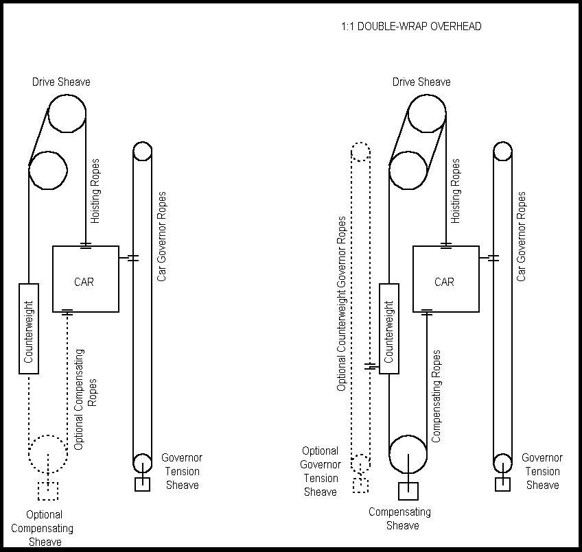
Figure 1. The 1:1 Gearless Elevator Configuration
2:1 Gearless Overhead
2:1 gearless traction elevators are also used in high speed applications for tall hoistways however they are typically used for shorter hoistways and lower speeds than their 1:1 cousins. Like the 1:1 machine the 2:1 gearless elevator consists of a traction sheave, brake drum and motor armature or rotor all mounted on a common shaft supported by two roller bearings. The main difference is the roping configuration which allows for a motor rotational speed that is double that employed in the 1:1 machine for the same car speed (and hence the use of smaller motor frames for the same horsepower). The gearless motor can be either A-C or D-C. They can be single or double wrapped as shown in Figure 2. below.
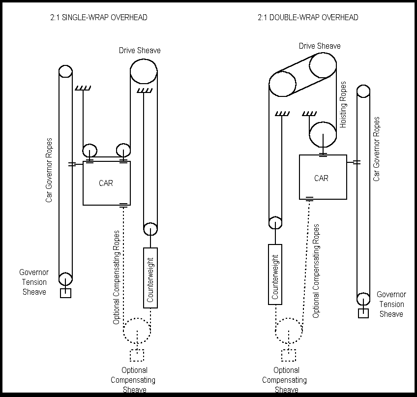
Figure 2. The 2:1 Gearless Elevator Configuration
1:1 Geared Overhead
The geared traction machine (Figure 3.) consists of the traction sheave, a worm or helical gear for power transmission, a brake, and an A-C or D-C hoist motor. They may be configured with either single or double wrap overhead drive shears as shown below.
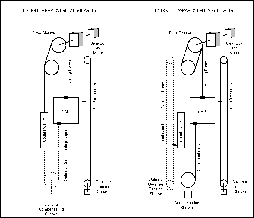
Figure 3. The 1:1 Geared Elevator Configuration
The Governor
The governor is a device actuated by the centrifugal force of whirling weights opposed by gravity. It is used in elevators as a standard safety measure to set an emergency mechanical brake that brings the car to a stop when the car exceeds a safe speed. A set of redundant safety features (both mechanical and electrical) are used in the elevator industry to ensure that cars do not run away. These safety measures depend on local and national codes and vary from country to country and even state to state. The interested reader is invited to read [1] should he/she be interested in learning more about them.
Compensating Ropes
Compensating ropes are used to compensate for the change in hoisting rope weight that occurs as a function of the position of the car in long hoistways. Basically, the use of compensating ropes insures that, for a given load, the motor sees the same inertia at all stops in the hoistway.
Double/Single Wrapping
The use of double wrapping provides substantially increased hoist rope traction surface area and is desirable in elevators with heavy loads. Hoist traction occurs between the hoisting ropes and grooves that are cast in the drive sheave. Figure 4 presents a cross section of two drive sheaves and represents the two most prevalent groove types used in the industry. As a rule of thumb the single wrap machines use the "V" groove and the double wrap machines use the "U" groove.

Figure 4. Drive Sheave Hoisting Rope Groove Types
Roping Configurations
Hoisting, compensating and governor roping standards have been established by the elevator industry and, like safety standards, vary from country to country. Elevator roping consists of cable made from steel strands that contain hemp or fiber cores. The composition breakdown in terms of cross-sectional area is approximately 48-52% steel 46-49% hemp/fiber and 2-3% air. To provide the reader with a feel for drive sheaves and roping a set of traction sheave/hoisting cable specifications is given below.
Table No. 2 Imperial Gearless Traction Sheave Data
|
Sheave Dia. [in] |
Groove Type |
No. Grooves |
Cable Dia. [in] |
Wrap |
|
24 |
V |
6 |
1/2-9/16-5/8 |
Single only |
|
26 |
U or V |
12 |
" |
Single or double |
|
28 |
U or V |
12 |
" |
" |
|
30 |
U or V |
12 |
" |
" |
|
33 |
U or V |
12 |
" |
" |
Fundamentals of Speed Reference Pattern Generation
In most A-C or D-C drive based elevator systems the positioning of the elevator is accomplished by the use of a speed reference "pattern" that provides the speed profile required to move the elevator car from the departure floor to the arrival floor in the minimum possible time with minimal discomfort to the passengers. The techniques used in the generation of these patterns are proprietary to each elevator o.e.m., however the following discussion, based on physical first principals, is general enough to avoid explication of proprietary details and provides the reader with a good understanding of what is involved in the generation of a pattern.
In any inertial system, rotational position is the pure integral of rotational speed. Speed is the approximate integral of torque with an integral time constant equal to the system inertia. In a translational system position is the pure integral of speed and speed is the pure integral of acceleration. From these observations it is clear that there is an approximate linear relationship between acceleration and torque. Similarly there is a linear relationship between the rate of change in torque and the rate of change in acceleration (or jerk rate). Based on the performance specifications presented in Table 1. a speed profile can be generated as follows:
Let the following nomenclature and units be used:
Position: xi [ft]
Speed: w [ft/sec] = [ft/min] /60
Acceleration: a [ft/sec^2]
Jerk: g [ft/sec^3]
Depending on the length of the run and the elevator configuration, one of three classes of speed profiles would be desirable. They are 1) using 100% Jerk (Figure 5.) , 2) Using 50% - 100% Jerk, (Figure 6.) 3) Using less than 50% Jerk (Figure 7.). The following Figures assume a 12 [ft] run with a maximum car speed of 325 [ft/min].
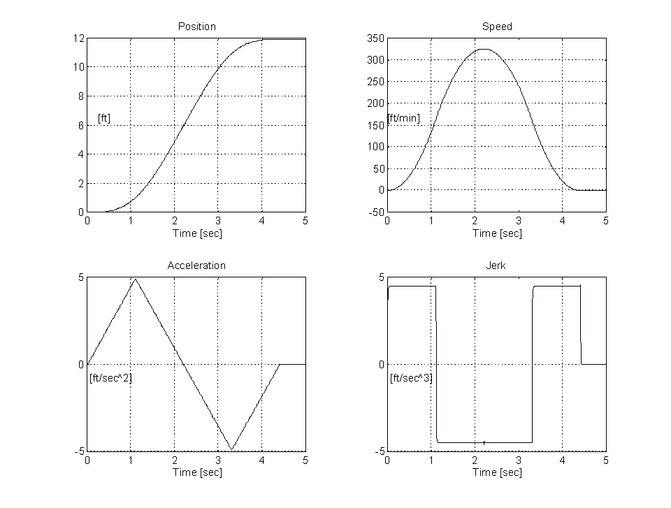
Figure 5. 12 [ft] Run, Speed Profile With 100% Jerk
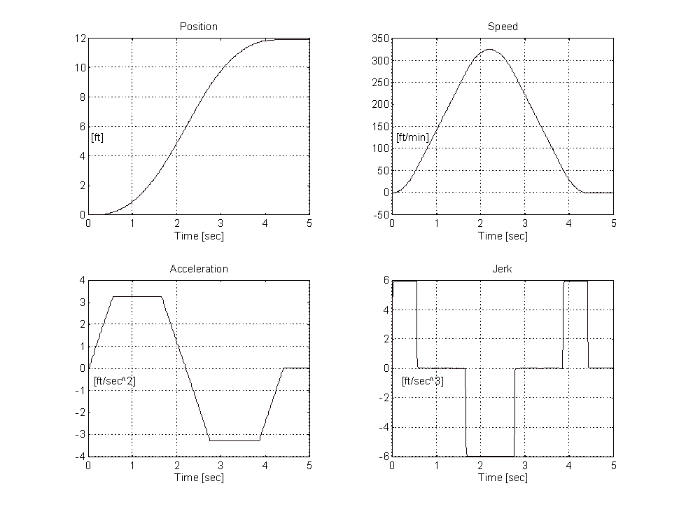
Figure 6. 12 [ft] Run, Speed Profile With 50% Jerk
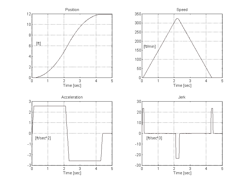
Figure 7. 12 [ft] Run, Speed Profile With 10% Jerk
By comparing Figures 5,6 and 7, the effect of decreasing the percentage of the run where jerk is non-zero results in higher jerk values (steeper acceleration and deceleration slopes) and lower acceleration values. The higher jerk rates are felt by the passenger in the car as discernible bumps at the beginning, middle and end of the ride. As the percentage of the run where the jerk is non-zero increases the acceleration rate also increases. When this value is 100% the rider feels the distinctive "over the falls" feeling around the middle of the ride. A typical percentage of jerk during a 1 floor run is between 50% and 80% (Figure 6. shows 50%). This results in jerk rates of 4 - 6 [ft/sec^3] and acceleration rates of 3 - 5 [ft/sec^2]. In general there should be no sharp edges in either the speed or acceleration profiles.
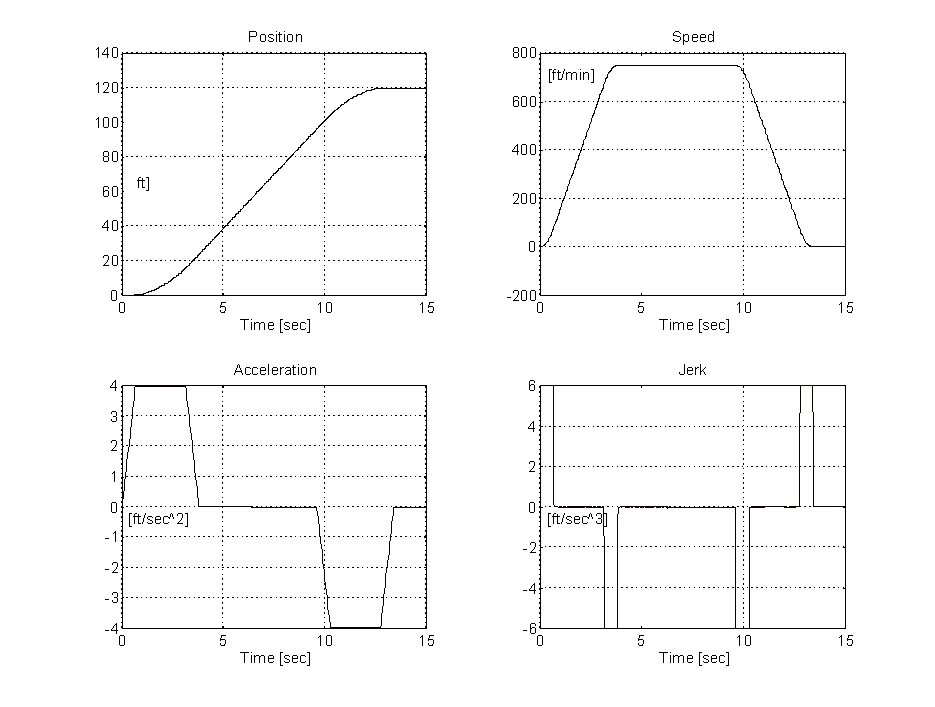
Figure 8. 120 [ft] Run, Speed Profile With 35% Jerk
Longer runs may require a different profile, for example a 10 floor run (120 [ft]) on a machine with a top speed of 750 [ft/min] that is tuned for a 6 [ft/sec^3] jerk and [4 ft/sec^2] acceleration would have a non-zero jerk rate for 35% of the accelerating and decelerating periods of the run (Figure 8.). For a given maximum speed, the floor-to-floor time on longer runs is dependent on the time it takes to accelerate the machine to full speed and decelerate from full speed to stop. These times are themselves dependent on the desired acceleration and jerk rates.
From the above examples it is intuitively obvious that a set of equations can be derived to describe the speed profile based on a user specified parameter set. The assumption that there is symmetry in the profile must be made to simplify the generation of the equations. Figure 9. represents a typical speed profile (or pattern) for a run where the percentage of the run where jerk is non-zero is less than 50%.
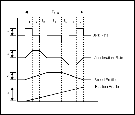
Figure 9. Constituent Parts of a Speed Profile
Assuming there is 1/4 symmetry in the jerk profile in Figure 9. (i.e T1 = T3 = T5 = T7 = Tg and T2 = T6 = Ta ), the following equations can be derived:
PROPRIETARY, If you would like more details send us an e-mail
Given any 4 of the 5 variables, The equations in (1.5) can be used to find the unknown variable.
The above discussion was intended to provide the reader with an intuitive understanding of the make-up of a typical speed profile or "pattern". While it does provide an analytical method for deriving speed profile acceleration and jerk rates, elevator vendors use a more heuristic approach. Discussion of these alternate approaches is outside the scope of this report.
The Typical Elevator Position Control Strategy
The use of a pattern to control the car is a feed forward control technique in so far as the position of the car is being controlled with speed. To provide the reader with an intuitive understanding of a way this strategy may be implemented the following discussion is presented.
Let two sets of limit switches be placed at 48" and 6", both sides of each floor in the elevator hoistway and an additional limit switch within 1/4" of the floor. These switches provide the pattern generation software with some information about the car position. This feedback may then be used to make slight corrections in the speed pattern and bring the car to within 1/4" of the floor at the time the car brake is set. One way these corrections may be made as follows:
When the car trips the limit switch at 48" from the floor the pattern generation software may either 1) compare the time that this occurs with a predicted time that is computed based on the desired speed profile or 2) log the speed error at the time the limit switch is tripped. Depending on the quantity and magnitude of the time or speed error a correction may then be made to the pattern to assure that the car will reach "leveling" speed (typically between 2 and 6 [ft/min]) before it reaches the limit switch that is 6" from the floor. By the time the car reaches this limit switch the speed feedback should match the predetermined "leveling" speed. The leveling speed and the distance from the floor to the limit switch (6"), may be used to compute the time at which the brake is to be set such that the car stops with less than 1/4" of error between the elevator car floor and the destination floor. Another approach would be to use a lower leveling speed and initiate the brake solenoid when the limit switch at the floor is tripped. The limit switch at the floor may also be used to verify car position when the elevator pattern software initiates a re-leveling procedure.
From the elevator o.e.m. perspective, the theoretically optimum drive performance results when the speed feedback matches the pattern exactly. The smaller the error (or the better the tracking) between the reference and the feedback the easier it is for the start-up engineer to set the pattern acceleration and deceleration rates along with the acceleration and deceleration jerk rates such that the desired floor-to-floor time is obtained (typically 4.5 to 5.5 [sec]). To achieve these floor-to-floor times the pattern generation software must be tuned such that the car is in a "leveling" speed condition for approximately 1/2 [sec] and this in turn requires that the speed feedback of the car reach leveling speed within 2" - 3" of the limit switch located at 6" from the destination floor. If the car's speed feedback exceeds the leveling speed when the limit switch that is 6" from the floor is tripped it is said to "overshoot" and the elevator pattern software initiates a re-leveling routine that significantly increases the floor-to-floor time of the ride. The above stated reasons, along with the need to minimize the correction to the pattern when the limit switch at 48" is tripped, imply that for satisfactory operation the drive system must provide excellent tracking of the speed reference pattern.
CHAPTER 2
THE TYPICAL AND PROPOSED CONTROL SYSTEM STRATEGIES
The Typical System Configuration and Control Design Philosophy
To realize tracking of the speed pattern that produces desirable floor-to-floor times, the speed loop in the typical control algorithm had to be tuned for approximately 15 [rad/sec]. Often this resulted in loop gains that excited low frequency system natural frequencies. This in turn resulted in the need to explore various frequency compensation techniques to attenuate the excited natural frequencies. Following is an excerpt from a typical Elevator Functional Specification [2]:
The purpose of the Maxpak III ® (Liftpak ®) elevator drive is to provide a high performance DC Drive for geared and gearless applications. The main feature of this drive will be that the speed loop will be capable of running at a scan rate of 5 [msec] w/o overload, which has proven to be necessary in high performance elevator applications. The speed loop must be able to run at 5[msec] with a feedback path lead/lag and a forward path lead/lag and lag, enabled. These blocks have been necessary to produce the proper speed loop response without exciting cable resonance, which can occur from 5 to 11 [Hz]. The 5 [msec] scan rate has minimized the phase shift at the resonance frequency and improved the phase margin at the speed loop crossover frequency.
The MaxPak III ® elevator drive should provide no less than the following speed loop performance for a drive tuned for 15 [rad/sec] speed loop bandwidth and the standard CML 150 [rad/sec] bandwidth:
- 5.0 [db] @ 5 [Hz]
- 110 degrees phase shift @ 5 [Hz]
Experience has shown that "hot" tuning of the speed loop results in loop gains that significantly amplify tachometer ripple. Resonance problems become more exacerbated when the once-per-revolution tachometer ripple disturbance frequency approaches a parasitic natural frequency. The resulting addition of energy at the parasitic natural frequency amplifies vibration in the car producing an unpleasant ride. The net result of high loop gains is a ride with vibrations that can be felt at various positions in the hoistway and various speeds. A forward path gain block and a function table was included in the typical control algorithm to help compensate for this. Briefly, in a system with noticeable tachometer ripple, the gain of the loop was attenuated at the speeds at which vibration was noticed. A system block diagram of the typical control algorithm is shown in Figure 10.
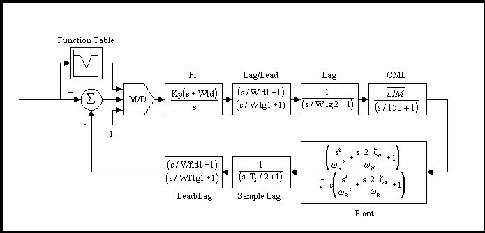
Figure 10. TYPICAL Elevator Functional Block Diagram
Figure 10. Nomenclature:
Kp: PI proportional gain term
Wld: PI lead frequency (Wld = Ki/Kp where Ki is the integral gain term)
Wld1: Forward path lead/lag block lead frequency
Wlg1: Forward path lead/lag block lag frequency
Wlg2: Forward path lag block lag frequency
 : Current Minor Loop (CML) gain term : Current Minor Loop (CML) gain term
Wfld1: Feedback path lead/lag block lead frequency
Wflg1: Feedback path lead/lag block lag frequency
Ts: Scan time of the speed loop (5 [msec] typically)
w N: The plant zero pair natural frequency
z N: The plant zero pair damping
w R: The plant pole pair natural frequency
z R: The plant pole pair damping
 : The system per-normal inertia : The system per-normal inertia
w CO: The speed loop crossover frequency
Tuning Strategy
 ; ;  ; ;
 ; ; 
 ; ; 

As shown above, tuning of the system shown in Figure 5. involves setting 3 lag frequencies, 3 lead frequencies and a gain term. The use of frequency compensation to attenuate system resonances is not trivial. Experience and an intimate knowledge of frequency domain analysis is usually required. This knowledge and experience enables the engineer commissioning the system to make intelligent adjustments based on observed behavior. The typical field service engineer from either the elevator vendor or the drive vendor does not have a background in frequency domain analysis and usually, out of frustration, abandons the adjustment of one or more of the frequency compensation blocks. Eventually the field service engineer relies on fine-tuning the function table and massaging the pattern generation software in conjunction with de-tuning the loop to achieve adequate ride quality. The author noted that typical speed loops in the field were typically de-tuned to around 7 - 10 [rad/sec]). These approaches negatively impact floor-to-floor times on short runs.
In the worst case the elevator consultant responsible for accepting the system would not accept the slower floor-to-floor times that resulted from de-tuning the speed loop and the pattern. After re-tuning he would then object to the noticeable vibrations that arose when the gain was increased to improve floor-to-floor times. This "catch-22" situation quickly became a source of contention between the drive system vendor, the elevator o.e.m. and the consultant. At the time of this writing some installations with typical elevator control strategies and drives were encountering situations similar to this that were yet to be resolved
Assuming, as shown above, frequency compensation blocks are used for attenuating system resonances other problems become apparent. The most noticeable of these is the loss of phase margin at the speed loop crossover that inevitably arises whenever high frequency attenuation is attempted. The loss of phase margin results in overshoot in the speed loop response. This then makes it difficult to set-up the pattern such that the leveling speed is achieved before the 6" limit switch is reached. When the speed loop overshoots, the usual solution is to adjust the trajectory of the pattern so that the car pattern reaches leveling speed at a point 4" to 8" from the 6" limit switch. This in turn results in a longer than desired leveling speed time (from 1 to 2 [sec]) and consequently longer floor-to-floor times. Another "catch-22" situation.
The Proposed System Configuration and Control Design Philosophy
The proposed design philosophy takes a different approach to solving the tracking problem. Rather than use a higher bandwidth in the speed loop to achieve adequate tracking, forcing on the reference was employed. With this approach the equivalent of a speed loop that responds like a 15 [rad/sec] loop w.r.t. the reference is possible while the actual closed loop bandwidth is only 5 [rad/sec]. The lower actual bandwidth of the closed speed loop significantly attenuates system natural frequencies that tended to be excited in typical systems. A resonance compensation circuit is employed in the speed feedback path to attenuate problematic system resonances. Because the compensation circuit is in the feedback path it tends to provide additional forcing w.r.t. the reference. The block diagram of the proposed system is presented in Figure 11.
PROPRIETARY, If you would like more details send us an e-mail
Figure 11. PROPOSED Elevator Functional Block Diagram
Figure 11. Nomenclature:
Kp: PI proportional gain term
Wld: PI lead frequency (Wld = Ki/Kp where Ki is the integral gain term)
 : Current Minor Loop (CML) gain term : Current Minor Loop (CML) gain term
Ts: Scan time of the speed loop (10 [msec] typically)
w N: The plant zero pair natural frequency
z N: The plant zero pair damping
w R: The plant pole pair natural frequency
z R: The plant pole pair damping
 : The system per-normal inertia : The system per-normal inertia
w RC: The res-comp filter center frequency
KRC: The res-comp filter gain
KF: The reference forcing filter forcing factor
w CO: The speed loop crossover frequency
Tuning Strategy
PROPRIETARY, If you would like more details send us an e-mail
Figure 12. Simulated Speed Profile for Figures 13, 14, 15 and 16.
In Figure 13. the better the tracking the higher the value of KF. The profile reference lies between the response for the 5 [rad/sec] loop without forcing (significant overshoot) and the loop responses with forcing (no overshoot). It is interesting to note that the responses with forcing come in "hard" to the floor. When setting up the system in the field this aspect of the use of forcing becomes attractive because the speed profile can be easily adjusted to ensure that the car comes into the floor with a minimum of leveling speed time.
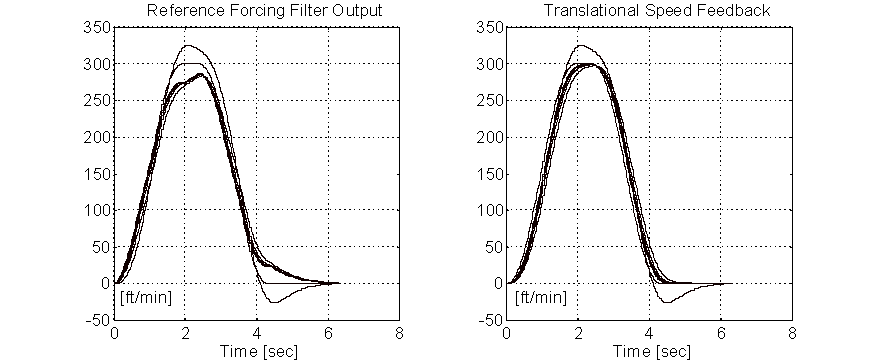
Figure 13. Speed Responses W & W/O Reference Forcing.
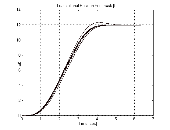
Figure 14. Position Responses W & W/O Reference Forcing.
Figure 14. shows clearly the negative effect of overshoot in the speed response on the position profile and the significant improvement realized the when forcing is used.
To demonstrate the effect of mismatch between the assumed crossover used to derive the coefficients in the forcing filter and the actual crossover, Figure 15. presents a collage of speed responses to the profile in Figure 12. The actual loop crossover varies from 2 [rad/sec] to 9 [rad/sec] in 2 [rad/sec] steps with KF fixed at 3. Note that the tracking is optimal when the actual crossover is equal to 5 [rad/sec], the bandwidth for which the forcing filter coefficients were set-up.
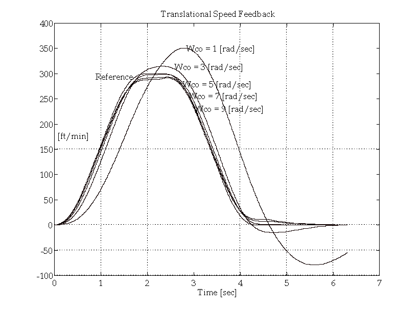
Figure 15. Effect of Reference Forcing with Incorrect Actual Bandwidth (Speed).
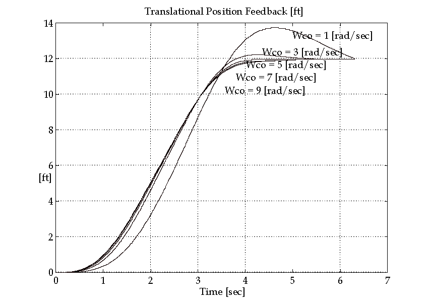
Figure 16. Effect of Reference Forcing with Incorrect Actual Bandwidth (Position).
In elevator applications the amount of forcing used is limited by the smoothness of the pattern. If the pattern generation software produces a very smooth pattern a forcing factor KF = 4 may be used. If it contains discontinuities in the derivative of speed a lower number will be required (to avoid forcing the discontinuities through the loop resulting in a "bumpy" ride). A good typical number to start with is KF = 2.
From (2.3) it is clear that the coefficients of the forcing filter are calculated based on the desired speed loop crossover wCO, the PI lead frequency Wld (also a function of the speed loop crossover frequency) and the forcing factor KF. Given that the filter is frequency sensitive, the discrete implementation requires the application of frequency warping to ensure that the effective time-domain responses are the same in both the discrete and continuous implementations. Following is a derivation of the forcing filter coefficients in a sampled system.
The forcing filter transfer function can be represented as:
PROPRIETARY, If you would like more details send us an e-mail
The Feedback Forcing (RES_COMP) Filter
PROPRIETARY, If you would like more details send us an e-mail
CHAPTER 3
THE 1:1 GEARLESS DYNAMIC MODEL
1:1 Gearless Physical Model
A graphical representation of the 1:1 gearless dynamic model is given in Figure 18. Several assumptions were made in the development of this model. They are:
The hoisting ropes are mass-less. This is the same as modeling a system with compensating ropes where the inertia of the ropes (eventually reflected to the motor) is lumped with the elevator and counterweight inertias. - The dynamics of the compensating roping are ignored.
- The dynamics of the governor roping are ignored.
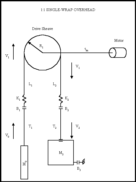
Figure 18. The 1:1 Gearless Physical Model
Tension in the hoisting roping is modeled with the same equations used to model strip/web in web transport systems. These models can be expanded to include the effects of material damping along with the non-linear dynamics associated with bulk movement of the material through tension zones. The fundamental equation used to model this behavior is given in (3.1). The derivation of this equation is found in Appendix A.
 ; (3.1) ; (3.1)
1:1 Gearless Physical First Principal Equations
The equations that describe the physical relationships between the elevator and counterweight masses and the hoistway roping are based on physical first principals and are given below in (3.2) through (3.8). Note that, to avoid muddying the physical description with unnecessary detail, these equations do not include non-linear effects such as stiction, non-linear dynamic and static friction, non-linear damping etc. which are included in the model.
 (3.2) (3.2)
 (3.3) (3.3)
 (3.4) (3.4)
 (3.5) (3.5)
 (3.6) (3.6)
 (3.7) (3.7)
 (3.8) (3.8)
The simulation of the 1:1 gearless elevator system is constructed based on the above equations.
1:1 Gearless Simulation Block Diagrams
Following are a set of block-diagrams that present the elements that compose the simulation of the 1:1 gearless elevator system contained in the MATLAB script file <s1_ng.m>.
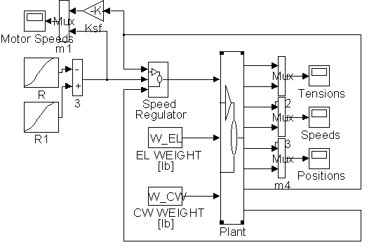
Figure 19. The 1:1 Gearless Simulink Model <s1_ng.m>
Figure 19 represents the complete Simulink Simulation. It contains a pattern generation circuit, represented by the two S-Curve blocks, a speed controller, which contains the speed loop shown in Figure 11, a plant model that is constructed based on equations (3.1) through (3.8), and a set of monitoring scopes for rope tensions, elevator and counterweight translational speeds and positions, along with the motor rotational speed reference and feedback.
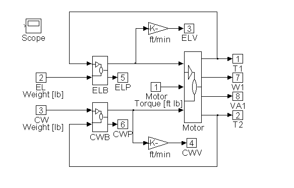
Figure 20. Detail of <Plant> in Figure 19.
Figure 20 contains block diagram representations of the three equation sets that comprise the plant model. They are the motor and roping equations, the elevator force and position equations and the counterweight force and position equations. Details of <ELB>, <CWB>, and <Motor> can be found in Figures 21, 22 and 23.
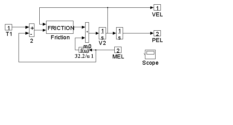
Figure 21. Detail of <ELB> in Figure 20.
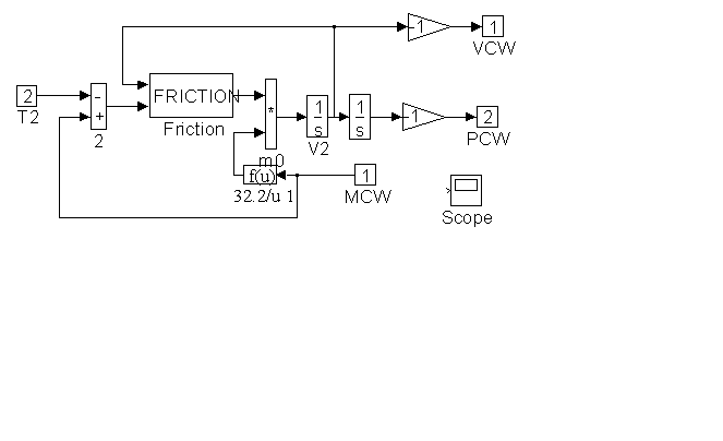
Figure 22. Detail of <CWB> in Figure 20
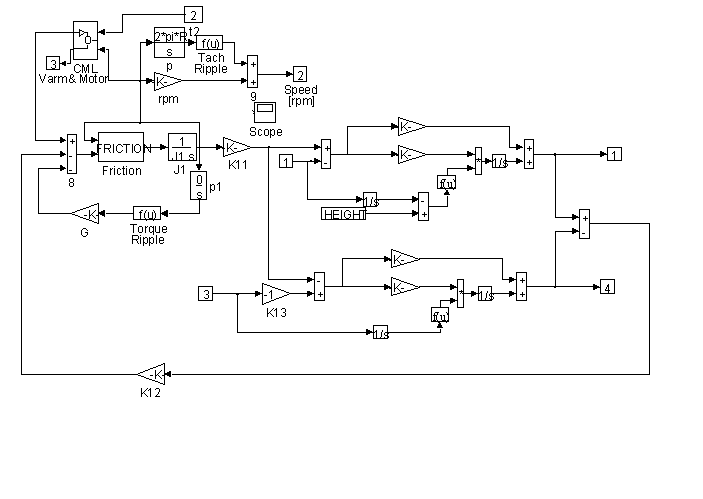
Figure 23. Detail of <MOTOR> in Figure 20
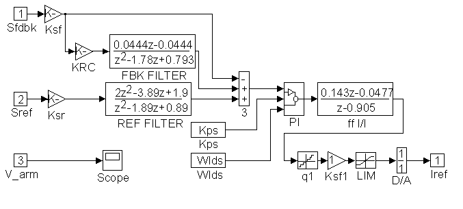
Figure 24. Detail of <SPEED REGULATOR> in Figure 19
The speed regulator in Figure 24 is composed of the same elements shown in Figure 11. In addition a lead/lag is included in the forward path for the purpose of investigation. The controller is implemented in the z-domain to include the effects of sampling. A proprietary PI model contains clamping and anti-saturation circuitry to protect against windup phenomena that can occur during the simulation when the PI output reaches pre-defined limits (+/- 4095 counts). In addition the entire controller implementation is in discrete counts. This is accomplished with the use of quantization blocks.
A proprietary friction model is incorporated in the models and can be identified with the name <FRICTION>. This block enables the system modeler to incorporate non-linear frictional effects such as the change in the coefficient of friction that occurs at the point when two surfaces in contact begin to move with respect to each other (force opposing movement due to the coefficient of static friction [or stiction] that changes to a coefficient of dynamic friction at minute speeds), the effect of windage losses that change according to a square law with respect to speed (such as motor windage losses, losses attributable to air pressure etc.) and constant frictional force offsets.
To initialize the simulation a script file <s1_u.m> was written. In addition to setting applicable physical constants in the Simulink work space, this file calculates controller parameters. A listing of <s1_u.m> for a typical run can be found in Appendix B. This file explicates the units and applicable unit conversions that are utilized in the simulation.
CHAPTER 4
THE 2:1 GEARLESS DYNAMIC MODEL
2:1 Gearless Physical Model
A graphical representation of the 2:1 gearless dynamic model is given in Figure 25. The same assumptions were made in the development of this model as those made in the development of the 1:1 gearless model. They are:
The hoisting ropes are mass-less. This is the same as modeling a system with compensating ropes where the inertia of the ropes (eventually reflected to the motor) is lumped with the elevator and counterweight inertias. - The dynamics of the compensating roping are ignored.
- The dynamics of the governor roping are ignored.
The following additional assumptions were also made:
The length of the ropes either side of the elevator and counterweight sheaves are approximately equal at all times during the simulation. - Springs are used to fasten the hoisting ropes to the "ground". If there are no springs the values for the spring constants and damping may be set very high to create a stiff connection.
- Springs are also used to connect the elevator and counterweight sheaves to the elevator and counterweight respectively. Again, if there are no springs the values for the spring constants and damping may be set very high to create a stiff connection.
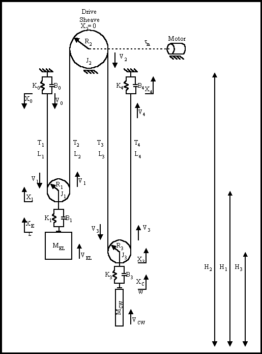
Figure 25. The 2:1 Gearless Physical Model
Similar to the 1:1 gearless model tension in the hoisting roping is modeled based on the same equation used to model strip/web in web transport systems (see (4.1) below and Appendix A). For detailed descriptions of the derivations of (4.5), (4.12), (4.16), and (4.19) see Appendix C.
 ; (4.1) ; (4.1)
2:1 Gearless Physical First Principal Equations
The equations that describe the physical relationships between the elevator and counterweight masses and the hoistway roping in the 2:1 gearless elevator model are based on physical first principals and are given below in (4.2) through (4.20). Note that, to avoid muddying the physical description with unnecessary detail, these equations do not include non-linear effects such as stiction, non-linear dynamic and static friction, non-linear damping etc. which are included in the model. The nomenclature used in the equations below can be found in Appendix D. This appendix contains a sample of the script file used to initialize the 2:1 gearless simulation. Units and appropriate unit conversions can also be found there.
 (4.2) (4.2)
 (4.3) (4.3)
 (4.4) (4.4)
 (4.5) (4.5)
 (4.6) (4.6)
 (4.7) (4.7)
 (4.8) (4.8)
 (4.9) (4.9)
 (4.10) (4.10)
 (4.11) (4.11)
 (4.12) (4.12)
 (4.13) (4.13)
 (4.14) (4.14)
 (4.15) (4.15)
 (4.16) (4.16)
 (4.17) (4.17)
 (4.18) (4.18)
 (4.19) (4.19)
 (4.20) (4.20)
A simulation of a 2:1 gearless elevator system can be constructed from the above equations.
2:1 Gearless Simulation Block Diagrams
Following are a set of block-diagrams that present the elements that compose the simulation of the 2:1 gearless elevator system contained in the MATLAB script file <s2_ng.m>.
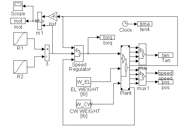
Figure 26. The 2:1 Gearless Simulink Model <s2_ng.m>
Figure 26 diagrams the complete Simulink Simulation of the 2:1 gearless simulation. It contains a pattern generation circuit, represented by the two S-Curve blocks, a speed controller, which contains the speed loop shown in Figure 11, a plant model that is constructed based on equations (4.2) through (4.20), and a set of file outputs for rope tensions, elevator and counterweight translational speeds and positions, and motor rotational speed reference and feedback.
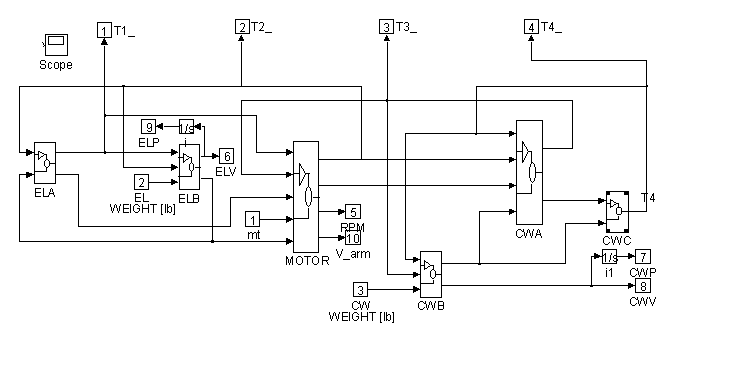
Figure 27. Detail of <Plant> in Figure 26.
Figure 27 contains block diagram representations of the equation that comprise the plant model. They are the motor and roping equations, the elevator force and position equations and the counterweight force and position equations. Details of <ELA>, <ELB>, <CWA>, <CWB>, <CWC>, and <MOTOR> can be found in Figures 28, through 33.
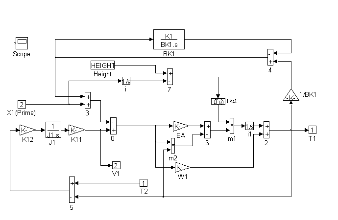
Figure 28. Detail of <ELA> in Figure 27.
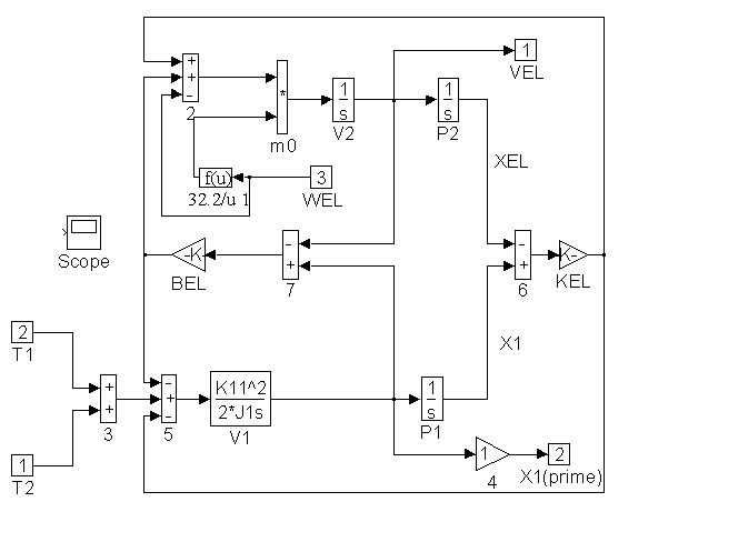
Figure 29. Detail of <ELB> in Figure 27
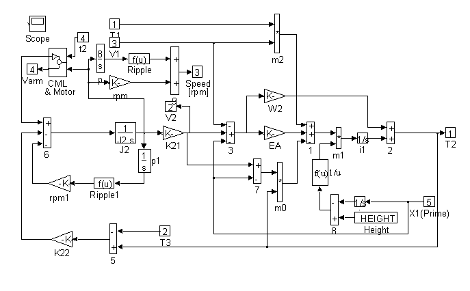
Figure 30. Detail of <MOTOR> in Figure 27
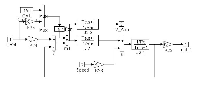
Figure 31. Detail of <CML> in Figure 30
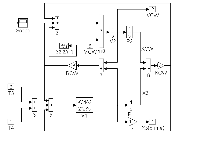
Figure 32. Detail of <CWB> in Figure 27
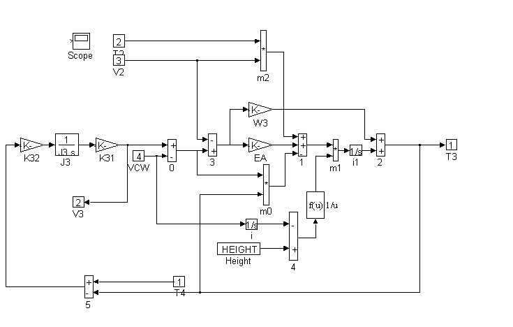
Figure 33. Detail of <CWA> in Figure 27
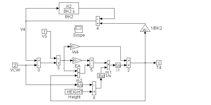
Figure 34. Detail of <CWC> in Figure 27

Figure 34. Detail of <SPEED REGULATOR> in Figure 26
The speed regulator in Figure 35 above is composed of the same elements shown in Figure 11. In addition a lead/lag is included in the forward path for the purpose of investigation. The controller is implemented in the z-domain to include the effects of sampling. A proprietary PI model contains clamping and anti-saturation circuitry to protect against windup phenomena that can occur during the simulation when the PI output reaches pre-defined limits (+/- 4095 counts). In addition the entire controller implementation is in discrete counts. This is accomplished with the use of quantization blocks.
Included in Figure 30 is a simulation of both tachometer and torque ripple. The integral of rotational speed is rotational position. Using the position information as the input to a correctly scaled sine wave generator a "once per tachometer revolution" disturbance can be summed with the speed feedback. This effectively mimics tachometer ripple. Similarly a "once per sheave revolution" disturbance can be injected into the torque summing junction to simulate torque ripple (such as would result in an improperly balanced sheave).
A proprietary friction model is incorporated in the model and can be identified with the name <FRICTION>. This block enables the system modeler to incorporate non-linear frictional effects such as the change in the coefficient of friction that occurs at the point when two surfaces in contact begin to move with respect to each other (force opposing movement due to the coefficient of static friction [or stiction] that changes to a coefficient of dynamic friction at minute speeds), the effect of windage losses that change according to a square law with respect to speed (such as motor windage losses, losses attributable to air pressure etc.) and constant frictional force offsets.
To initialize the simulation a script file <s2_u.m> was written. In addition to setting applicable physical constants in the Simulink work space, this file calculates controller parameters. A listing of <s2_u.m> for a typical run can be found in Appendix C. This file explicates the units and any applicable unit conversions that are utilized in the 2:1 gearless simulation.
CHAPTER 5
THE 1:1 GEARED DYNAMIC MODEl
1:1 Geared Physical Model
A graphical representation of the 1:1 geared dynamic model is given in Figure 36. Several assumptions were made in the development of this model. They are:
The hoisting ropes are mass-less. This is the same as modeling a system with compensating ropes where the inertia of the ropes (eventually reflected to the motor) is lumped with the elevator and counterweight inertias. - The dynamics of the compensating roping are ignored.
- The dynamics of the governor roping are ignored.
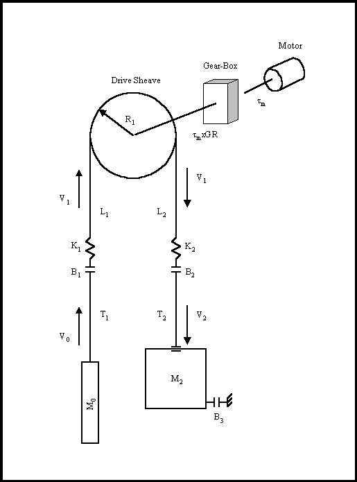
Figure 36. The 1:1 Gearless Physical Model
Tension in the hoisting roping is modeled using the same equations used to model strip/web in web transport systems. These models can be expanded to include the effects of material damping along with the non-linear dynamics associated with bulk movement of the material through tension zones. The fundamental equation used to model this behavior is given in (5.1). The derivation of this equation is found in Appendix A.
 ; (5.1) ; (5.1)
1:1 Gearless Physical First Principal Equations
The equations that describe the physical relationships between the elevator and counterweight masses, the hoistway roping and the motor/gear-box are based on physical first principals and are given below in (5.2) through (5.8). Note that, to avoid muddying the physical description with unnecessary detail, these equations do not include non-linear effects such as stiction, non-linear dynamic and static friction, non-linear damping, gear-backlash etc. which are included in the model.
 (5.2) (5.2)
 (5.3) (5.3)
 (5.4) (5.4)
 (5.5) (5.5)
 (5.6) (5.6)
 (5.7) (5.7)
 (5.8) (5.8)
A simulation of a 1:1 gearless elevator system can be constructed from the above equations.
1:1 Gearless Simulation Block Diagrams
Following are a set of block-diagrams that present the elements that compose the simulation of the 1:1 gearled elevator system contained in the MATLAB script file <s1_g.m>.
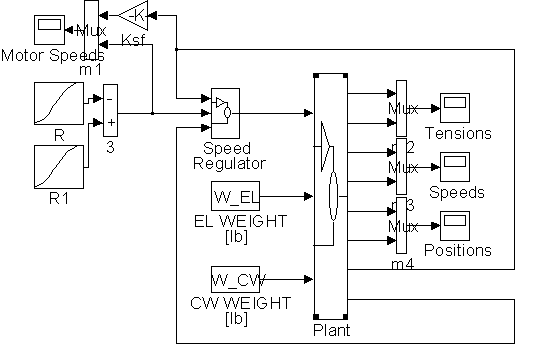
Figure 37. The 1:1 Geared Simulink Model <s1_ng.m>
Figure 37 diagrams the complete Simulink Simulation. It contains a pattern generation circuit, represented by the two S-Curve blocks, a speed controller, which contains the speed loop shown in Figure 11, a plant model that is constructed based on equations (5.1) through (5.8), and a set of monitoring scopes for rope tensions, elevator and counterweight translational speeds and positions, and motor rotational speed reference and feedback.

Figure 38. Detail of <Plant> in Figure 37.
Figure 38 contains block diagram representations of the three equation sets that comprise the plant model. They are the motor and roping equations, the elevator force and position equations and the counterweight force and position equations. Details of <ELB>, <CWB>, and <Motor> can be found in Figures 39, 40 and 42.
Figure 39. Detail of <ELB> in Figure 38.
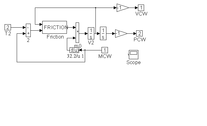
Figure 40. Detail of <CWB> in Figure 38
The speed regulator in Figure 41 below is composed of the same elements shown in Figure 11. In addition a lead/lag is included in the forward path for the purpose of investigation. The controller is implemented in the z-domain to include the effects of sampling. A proprietary PI model contains clamping and anti-saturation circuitry to protect against windup phenomena that can occur during the simulation when the PI output reaches pre-defined limits (+/- 4095 counts). In addition the entire controller implementation is in discrete counts. This is accomplished with the use of quantization blocks.

Figure 41. Detail of <SPEED REGULATOR> in Figure 37
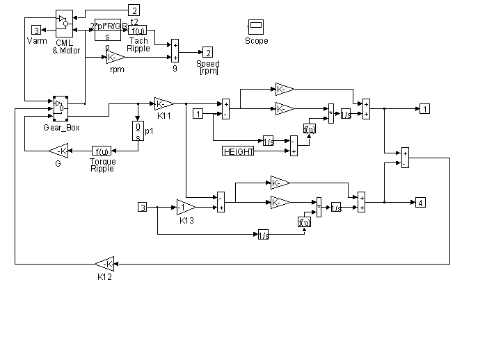
Figure 42. Detail of <MOTOR> in Figure 38
Included in Figure 48 is a simulation of both tachometer and torque ripple. The integral of rotational speed is rotational position. Using the position information as the input to a correctly scaled sine wave generator a "once per tachometer revolution" disturbance can be summed with the speed feedback. This effectively mimics tachometer ripple. Similarly a "once per sheave revolution" disturbance can be injected into the torque summing junction to simulate torque ripple (such as would result in an improperly balanced sheave).
The gear-box model includes the effects of stiction. viscous damping, windage, and gear backlash. A proprietary friction model is incorporated in the model to provide realistic non-linear friction dynamics. This block can be identified with the name <Friction>..
To initialize the simulation a script file <s1_ug.m> was written. In addition to setting applicable physical constants in the Simulink work space, this file calculates controller parameters. A listing of <s1_ug.m> for a typical run can be found in Appendix E. This file explicates the units and any applicable unit conversions that are utilized in the simulation.
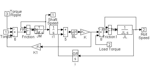
Figure 43. Detail of <Gear_Box> in Figure 42
CHAPTER 6
SIMULATION RESULTS
The models presented in chapters 3, 4 and 5 were used to fill in the matrix of simulations shown below in Table 3. The simulations provided the groundwork for later verification with field testing and formed the basis upon which the final proposed design was built. Note that a simulation of an unloaded elevator going up is approximately dynamically equivalent to a simulation a fully loaded car going down and visa - versa. For this reason only simulations of runs in the up direction were necessary.
Table No. 3
| |
Loaded |
Balanced |
Empty |
|
1:1 (CH. 2) |
Rope Tensions |
Rope Tensions |
Rope Tensions |
|
Plots |
Rot. Spd. |
Rot. Spd. |
Rot. Spd. |
|
" |
Trans. Spd. |
Trans. Spd. |
Trans. Spd. |
|
" |
Trans. Pos. |
Trans. Pos. |
Trans. Pos. |
|
2:1 (CH. 3) |
Rope Tensions |
Rope Tensions |
Rope Tensions |
|
Plots |
Rot. Spd. |
Rot. Spd. |
Rot. Spd. |
|
" |
Trans. Spd. |
Trans. Spd. |
Trans. Spd. |
|
" |
Trans. Pos. |
Trans. Pos. |
Trans. Pos. |
|
1:1 (CH. 4) |
Rope Tensions |
Rope Tensions |
Rope Tensions |
|
Plots |
Rot. Spd. |
Rot. Spd. |
Rot. Spd. |
|
" |
Trans. Spd. |
Trans. Spd. |
Trans. Spd. |
|
" |
Trans. Pos. |
Trans. Pos. |
Trans. Pos. |
The simulated system was composed of a 20 floor - 12 ' per floor hoistway with a 2500 [lb] elevator and hoisting roping weight, a 2000 [lb] capacity, and an 3500 [lb] counterweight. The motor in each simulation was sized to provide a per-normal reflected inertia of 1.5 [sec] unloaded. For all the simulations the cabling was chosen to consist of six - 5/8" ropes in a U groove drive sheave (maximum traction). The simulations were performed for a one-floor run in the up direction going from the 18th floor to the 19th floor. Damping terms were adjusted heuristically to mimic observed elevator behavior. For the run speed profile the maximum acceleration rate was set at 4 [ft/sec^2], the jerk rate was set at 6 [ft/sec^3], the run time was at 4.2 [sec] and the top speed was set at 330 [ft/sec].
For each condition presented in table 3 a set of simulations of the proposed scheme(with compensation) is followed by a set of typical simulations (without compensation). The bandwidth of the speed loop was set to 5 [rad/sec] with 3.5 : 1 reference forcing used in the simulations of the proposed scheme. Tachometer ripple was included and was set a 5% of set speed. To demonstrate the negative effects of increasing bandwidth, a select set of plots shows the effect of increasing gain in the typical design to achieve tracking similar to the proposed design.
1:1 Gearless Simulation (Chapter 3.)
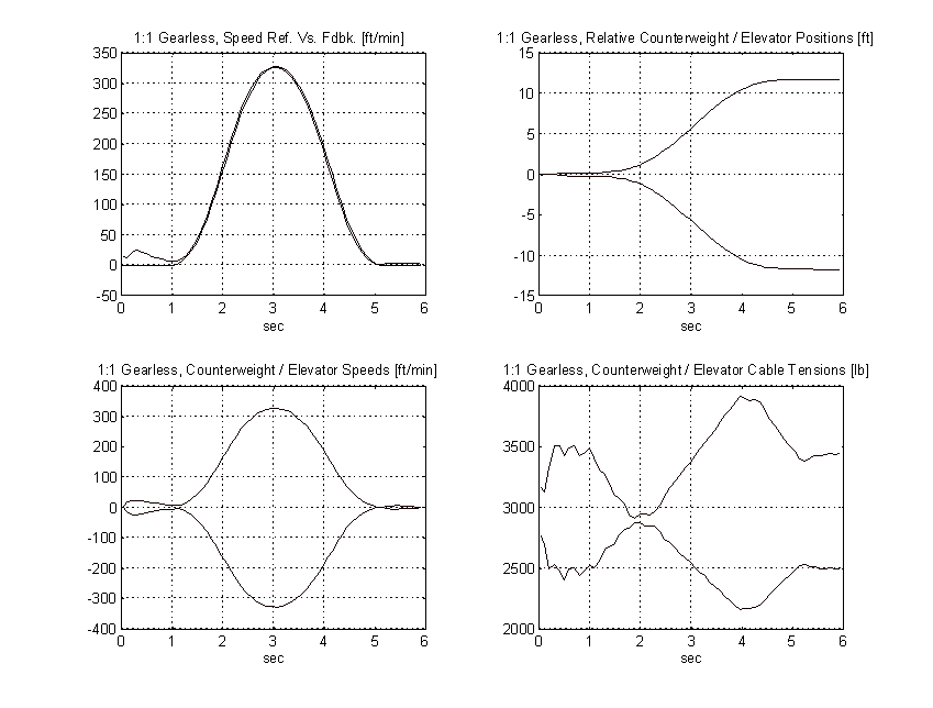
Figure 44. 1:1 Gearless Simulation, No Load, PROPOSED
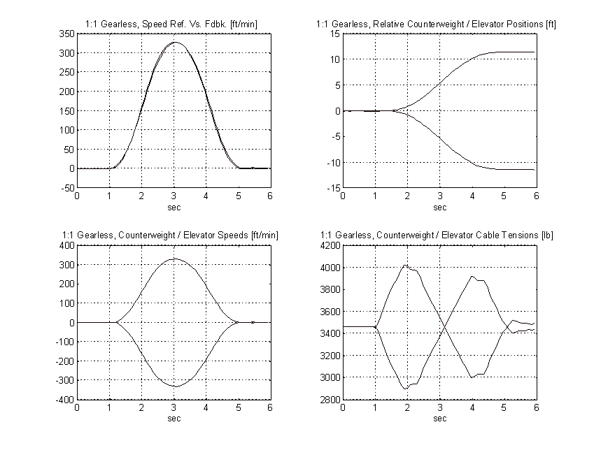
Figure 45. 1:1 Gearless Simulation, Balanced Load, PROPOSED
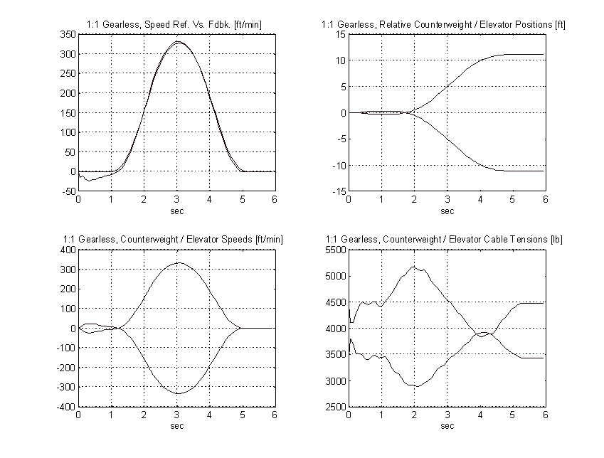
Figure 46. 1:1 Gearless Simulation, Full Load, PROPOSED
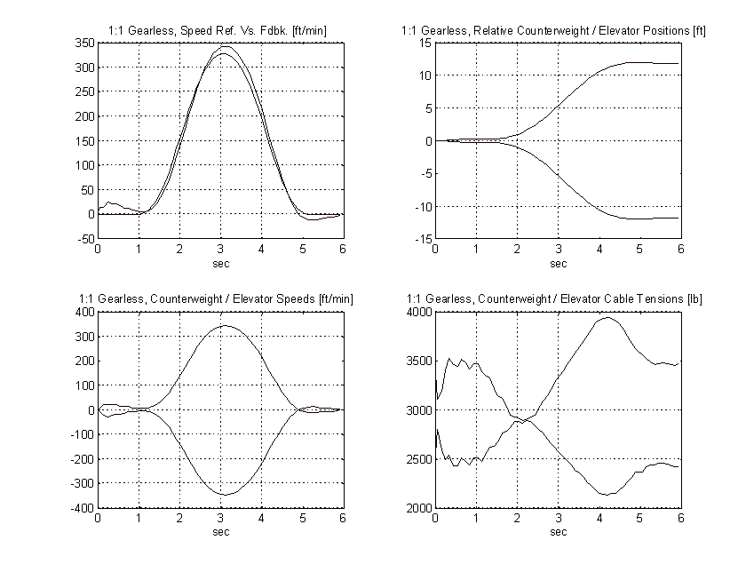
Figure 47. 1:1 Gearless Simulation, No Load, TYPICAL
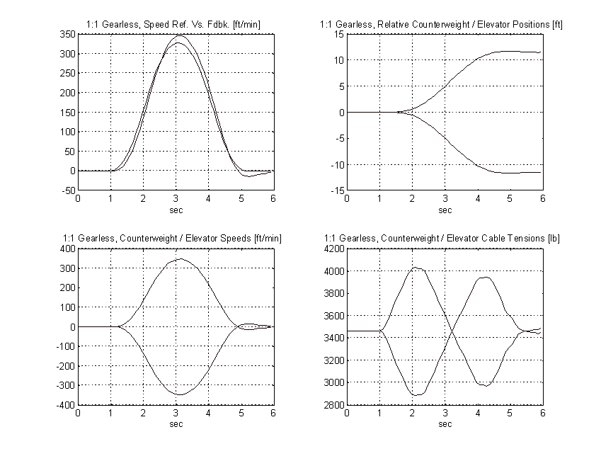
Figure 48. 1:1 Gearless Simulation, Balanced Load, TYPICAL
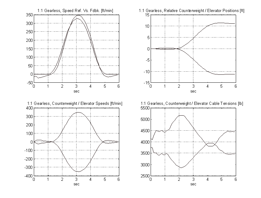
Figure 49. 1:1 Gearless Simulation, Full Load, TYPICAL
From the above plots it is clear that to obtain the same pattern tracking as the proposed system, the gain on the typical system must be increased by a factor of three or more. Figure 50 shows the effect of a 3:1 gain increase has on the above system. Note the tachometer ripple and low frequency system resonances and their effect on the speed of the elevator.

Figure 50. 1:1 Gearless Simulation, Full Load, TYPICAL, 3:1 Gain Increase
2:1 Gearless Simulation (Chapter 3.)
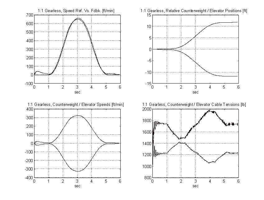
Figure 51. 2:1 Gearless Simulation, No Load, PROPOSED
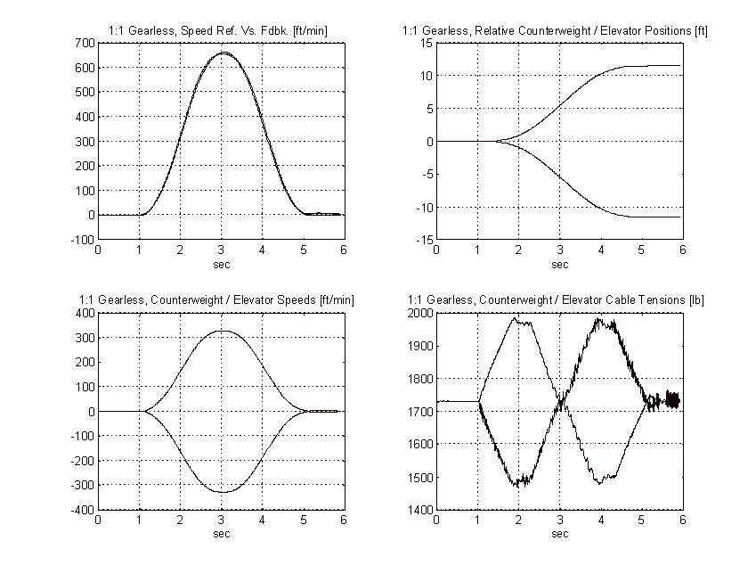
Figure 52. 2:1 Gearless Simulation, Balanced Load, PROPOSED
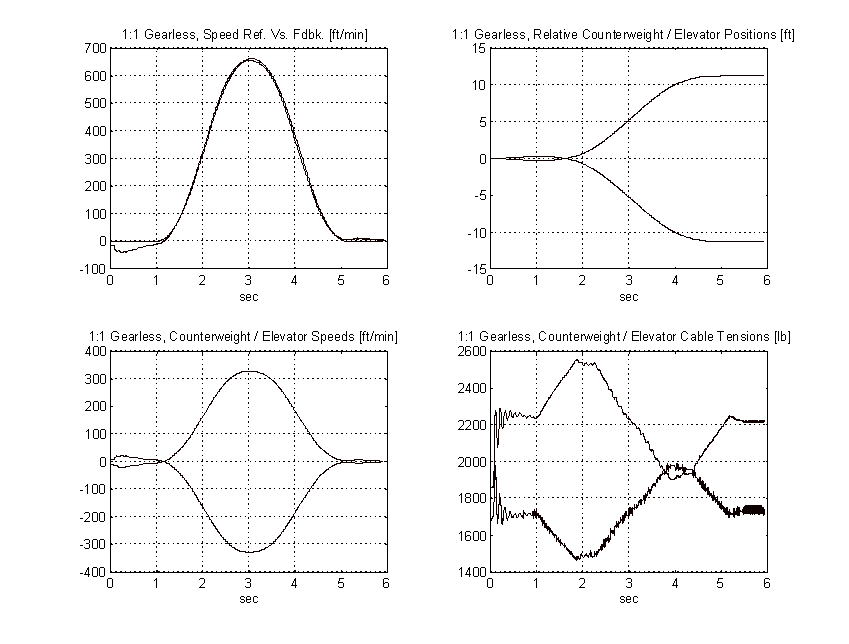
Figure 53. 2:1 Gearless Simulation, Full Load, PROPOSED
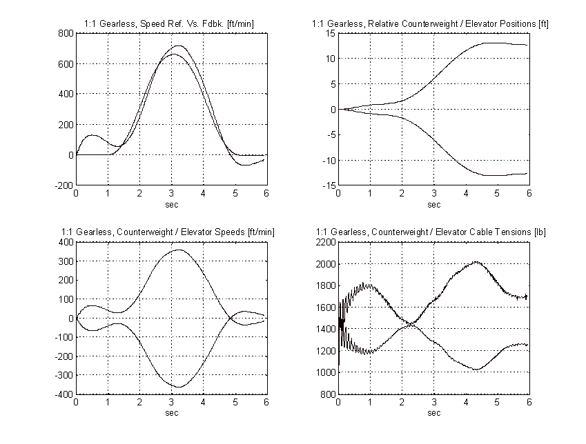
Figure 54. 2:1 Gearless Simulation, No Load, TYPICAL
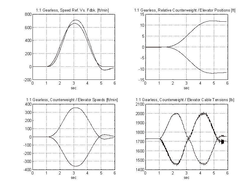
Figure 55. 2:1 Gearless Simulation, Balanced Load, TYPICAL
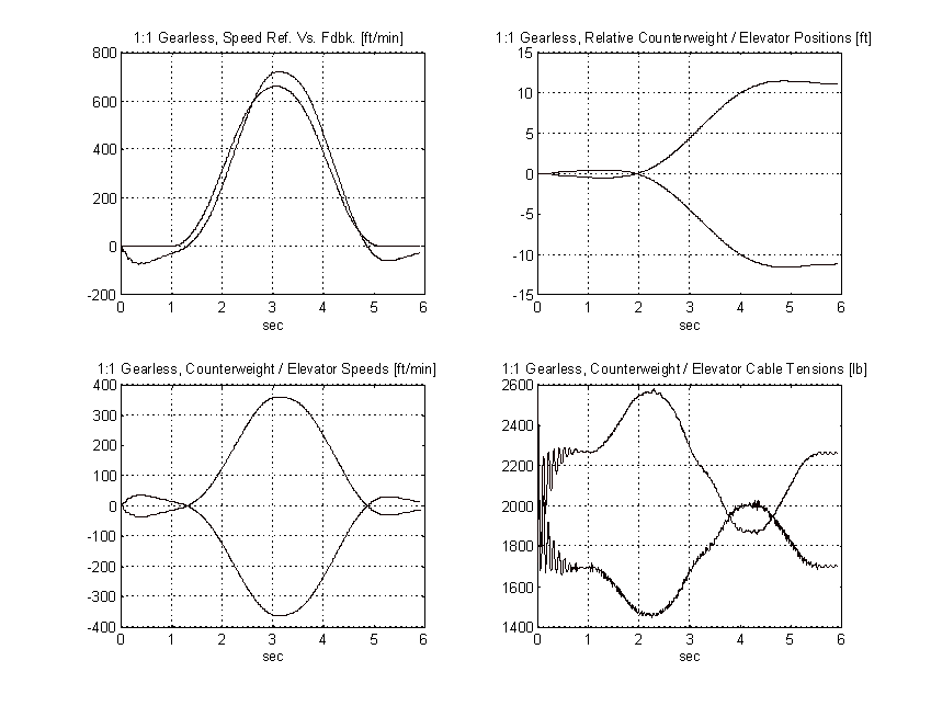
Figure 56. 2:1 Gearless Simulation, Full Load, TYPICAL
From the above plots it is clear that to obtain the same pattern tracking as the proposed system, the gain on the typical system must be increased by a factor of three or more. Figure 57 shows the effect of a 3:1 gain increase has on the above system. Note the tachometer ripple and low frequency system resonances and their effect on the speed of the elevator.
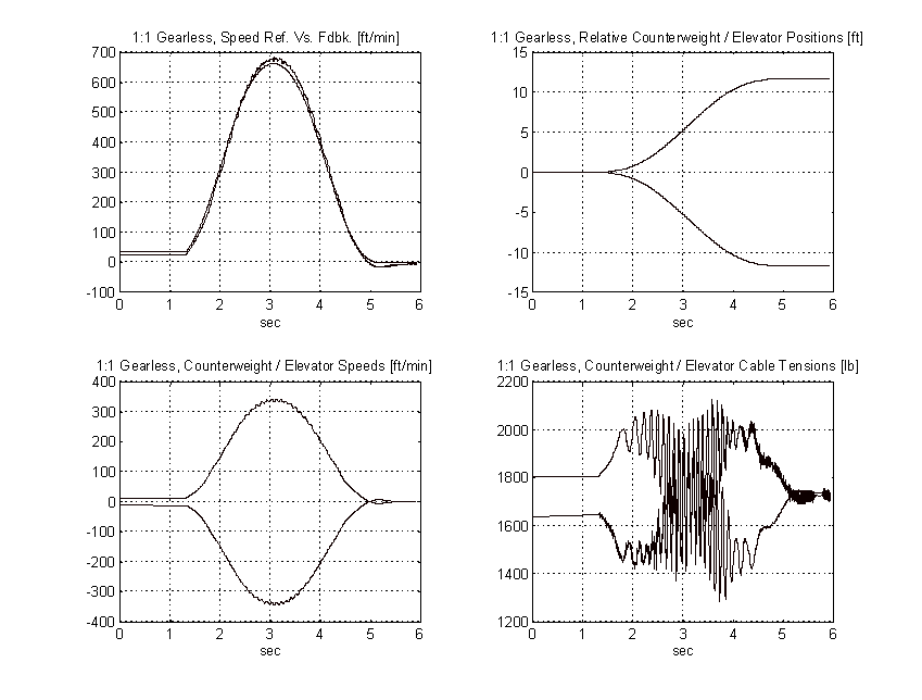
Figure 57. 2:1 Gearless Simulation, Balanced Load, TYPICAL, 3:1 Gain Increase
1:1 Geared Simulation (Chapter 4.)
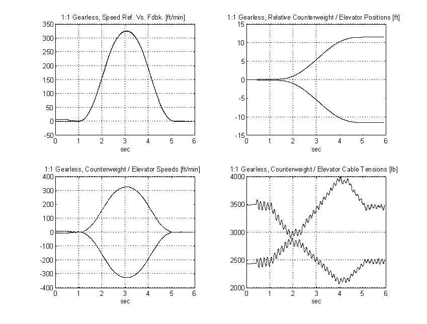
Figure 58. 1:1 Geared Simulation, No Load, PROPOSED
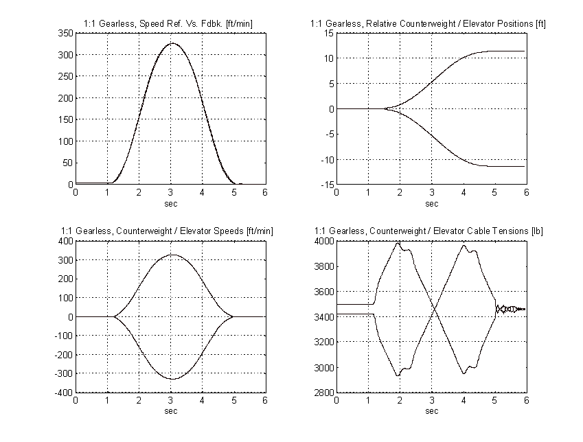
Figure 59. 1:1 Geared Simulation, Balanced Load, PROPOSED
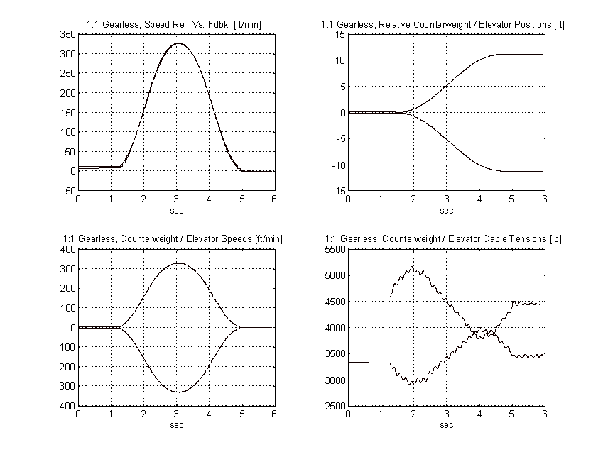
Figure 60. 1:1 Geared Simulation, Full Load, PROPOSED
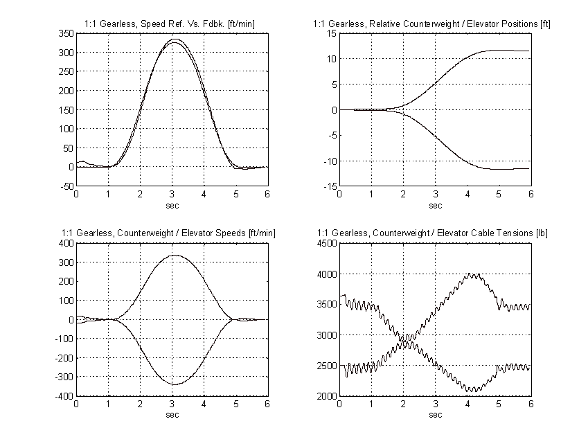
Figure 61. 1:1 Geared Simulation, No Load, TYPICAL
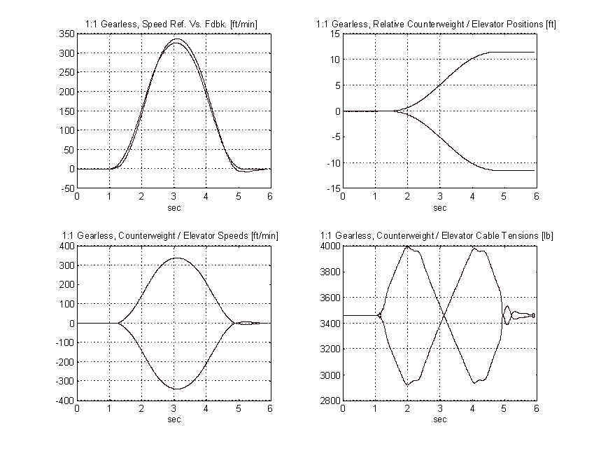
Figure 62. 1:1 Geared Simulation, Balanced Load, TYPICAL
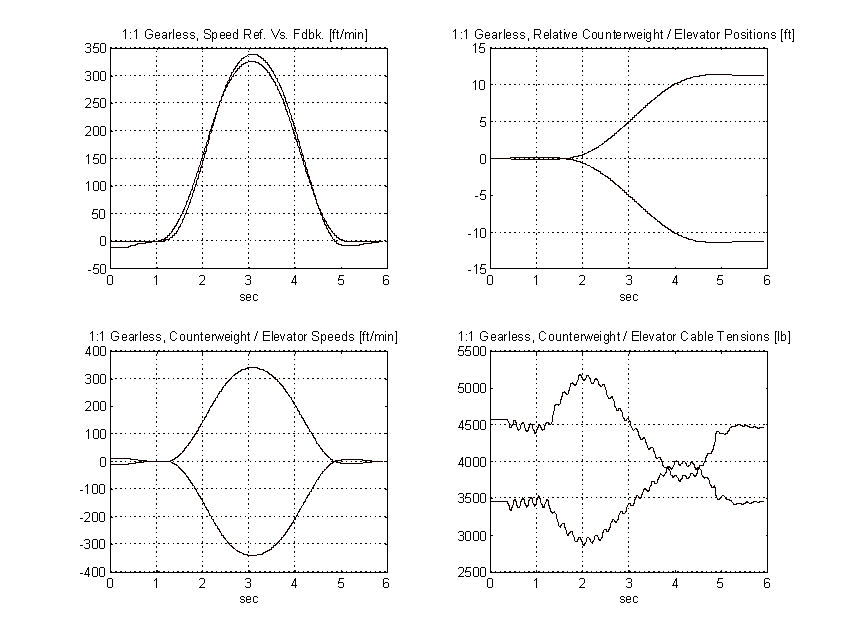
Figure 63. 1:1 Geared Simulation, Full Load, TYPICAL
From the above plots it is clear that to obtain the same pattern tracking as the proposed system, the gain on the typical system must be increased by a factor of three or more. Figure 64 shows the effect of a 3:1 gain increase has on the above system. Note the tachometer ripple and low frequency system resonances and their effect on the speed of the elevator.
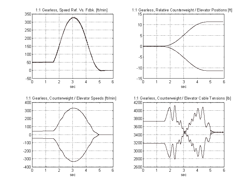
Figure 64. 1:1 Geared Simulation, No Load, TYPICAL, 3:1 Gain Increase
CHAPTER 7
PROPOSED START-UP RESULTS
Hyatt Regency Chicago
The proposed control system configuration was field tested at the Hyatt Regency, Chicago IL. This site had proven extremely problematic and until the proposed software was introduced the consultant would not accept the elevators.
The Hyatt Regency Towers is comprised of an east and west wing. The east wing contains 6 double-wrapped 2:1 gearless elevators and the west wing contains 6 double wrapped 1:1 gearless elevators. The combination of elevator/counterweight weights, cabling, and hoistway heights in both the east and west wings produced dominant low frequency parasitic resonances in the range of 5 to 10 [Hz]. In addition, all of the elevator speed feedbacks exhibited significant tachometer ripple (approximately 2-3% of set-point).
The typical configuration could be tuned up (with a bandwidth of approximately 9 - 10 [rad/sec]) to provide adequate tracking at the cost of producing significant vibration in the elevator ride, especially at the top of the hoistway. When the drive was de-tuned (to approximately 5 [rad/sec]) to alleviate the ride vibration, poor tracking resulted in overshoot and the pattern had to be significantly softened increasing the floor-to-floor times to unacceptable levels.
The proposed configuration was installed and tuned for 5 [rad/sec] with a forcing factor of 4 on the reference. The tracking was improved dramatically, however the combination of a high forcing factor and discontinuities in the derivative of the speed pattern at the end of the ride resulted in disturbances that were forced through controller and felt in the elevator as discernible bumps. The elevator vendor responsible for the installation, was requested to address the problem and produced a pattern with a much smoother derivative. The forcing factor on the reference filter was reduced to 2 and the speed regulator was tuned for 5 - 6 [rad/sec]. The tracking variable was adjusted to provide optimum tracking as described in Chapter 2, and the resulting ride was significantly smoother than that obtained with the typical configuration. The floor to floor times were consistently between 4.5 and 5 [sec] for both up and down one-floor runs at all stations in the hoistway. There was NO overshoot in the speed response therefore the elevator came in "hard" to the destination floor resulting in leveling speed times of 0.5 - 0.7 [sec]. The flight times for all single floor runs was consistently 7.5 - 7.7 [sec]. This compares with one-floor flight times of 9.5 - 10.5 [sec] with the typical implementation.
Tuning The PROPOSED Drive and Consistency of Tuning Parameters
A field service engineer from the drive vendor was assigned to tune the proposed system using only the tuning tools described in Chapter 2. After an initial learning curve of several hours the drive vendor engineer tuned the elevator such that the response described above was achieved. A representative from the elevator vendor was then asked to tune the drives independently and noted the following:
- Five of the six elevators in the west wing (1:1 gearless) were tuned with exactly the same drive tuning parameters and exactly the same pattern set-up parameters as those obtained by the drive vendor field service engineer.
- One of the six elevators in the west wing required the use of the RES_COMP filter on the feedback. This then required a different set of pattern generation set-up values to produce the same floor-to-floor and flight times as the other 5 elevators.
- All six elevators in the east wing (2:1 gearless) were tuned with exactly the same drive tuning parameters and exactly the same pattern set-up parameters.
- The pattern set-up for the 2:1 gearless in the east tower was the same as the pattern set-up for the 5 elevators that were tuned in the east tower that did not require the use of the RES_COMP feedback filter.
The elevator vendor and the drive vendor service engineers experimented with the RES_COMP filter on the feedback and noted that its use adversely impacted the tracking of the pattern. To produce floor-to-floor times similar to the installed systems that did not use the RES_COMP filter some customization of the pattern set-up parameters was required. They did note however, that the RES_COMP filter provided adequate suppression of the parasitic natural frequency.
The general consensus from the field was that there was much less "fudging" required in the set-up and tuning of the proposed system when compared to the typical system. They noted that it was the number of variables available for adjustment (tracking, RES_COMP, and crossover) was less in the proposed control algorithm than the typical control algorithm (three leads, three lags and a gain term). They also noted that the functionality of the proposed tuning parameters were fundamentally different from the typical tuning parameters. In general they noted that individuals who are used to tuning the typical system would benefit significantly from some field experience and/or training in tuning the proposed control algorithm.
It is the authors impression that field service engineering personnel who are used to tuning the typical drive will require training in order to become familiar with the proposed tuning philosophy. However those individuals who are using the proposed scheme for the first time will find the controller tuning strategy significantly easier to learn than the typical strategy would have been.
CHAPTER 8
OBSERVATIONS AND CONCLUSIONS
Observations/Conclusions
The following is a summary of observations and conclusions made from simulations of the three elevator models and field testing of the proposed control algorithm at the Hyatt Regency, Chicago Illinois.
- Higher speed loop bandwidths in elevator applications result in forward path gains that significantly amplify tachometer ripple. At particular speeds, the amplified tachometer ripple excites parasitic natural frequencies. This is especially noticeable when these frequencies are in the 5 - 10 [Hz] range.
- Higher speed loop bandwidths reduce damping of the dominant resonant frequency. This is especially noticeable when this frequency is below 10 [Hz].
- To realize similar tracking of the pattern, elevator systems using the typical control algorithm required speed loop bandwidths approximately 2 to 3 times higher than the proposed control algorithm.
- The use of the reference forcing filter in the proposed control algorithm significantly improves tracking of the pattern without the need for high speed loop bandwidths. Lower speed loop bandwidths translate into significant attenuation of parasitic resonant frequencies and reduced excitation of these frequencies by tachometer ripple. This in turn translates into a smoother ride.
- The use of the reference forcing filter in the proposed control algorithm results in a speed response that is first order. The step response does not have any overshoot. By coming into the target floor with no overshoot the time spent in leveling speed is reduced resulting in significantly improved floor-to-floor times.
- In systems where the dominant natural frequency is very low and under-damped the RES_COMP filter can be deployed to attenuate the parasitic frequency. This will require some adjustment to the pattern if a floor-to-floor time similar to that obtained without the RES_COMP filter is desired.
BIBLIOGRAPHY
[1] NEMA, "Elevator Industry Safety Standards"
[2] Carey, Jim. "The Functional Specification For The Liftpak Elevator Drive", May 1993, Reliance Electric Internal Document.
[3] B. T. Boulter, "Writing Difference Equations for Filters.", SR. 3 ApICS Internal Systems Engineering Document
[4] Fox, H. J., Boulter, Brian T., "Advanced Dynamic Simulation", Chapters 4 and 5, Internal ApICS Systems Engineering Course.
|