APPLIED INDUSTRIAL CONTROL SOLUTIONS
ApICS LLC.
BENDING LOSS CALCULATIONS
BRIAN T. BOULTER, HARRY W. FOX
© ApICS ® LLC 2000
ABSTRACT
This report presents a mathematical model for estimating roll-by roll bending losses and tension build-up required in strip material as it bends and straightens while traveling through a network of powered and unpowered rolls in a process line. The total horsepower required for the drag and drive bridles in strip process lines depends not only on process throughput parameters, such as tension set points and process line speed, but on the summation of the various losses encountered along the line. Methods are described for continuous tracking of strip fiber deformation on a roll-by-roll basis beginning at the process line entry section. Such an analysis of bending losses is desirable when encountering rolls of varying diameters, for which the steady-state analysis of the literature is no longer valid.
INTRODUCTION
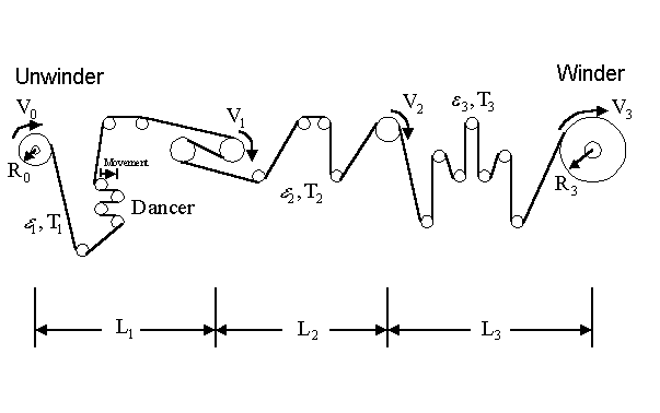
An example strip process line shown in Figure 1, in which the material passes from an unwinder section, through a number of sections consisting of rollers of various sizes, to a terminating winder section. The straining of the material as the strip bends on the rolls and straightens between the rolls can require additional unrecoverable work by the drive motors, particularly whenever portions of the strip fibers undergo plastic deformation. Thus, a certain amount of bending loss, often reflected added tension build-up, can occur at each of the rollers.

Figure 1. Example strip process line
The total horsepower required for the drag and drive bridles in metal strip process lines depends not only on process throughput parameters, such as tension set points and process line speed, but on the summation of the various losses encountered along the line. A serious underestimation of the process line tension needs could be disastrous, in that the desired product specifications can not be met. Extravagantly over sizing the bridle drives, on the other hand, can increase the cost without any net advantage.
An analysis of the tension distribution along the process line is usually undertaken to determine the most favorable horsepower distribution, since it is desirable to utilize all the horsepower specified. The installed power, which needs to be kept to minimum, corresponds to the power needed for strip deformation, bridle input and output tension differences, and to account for mechanical losses.
This report presents a mathematical model for estimating the tension change that takes place as the metal strip bends and straightens during its travels through the network of powered and unpowered rolls in the process line. The tension build up due to bending is often neglected for rolls not found in a tension-leveler section of the process line. The model described in this report shows how bending-loss estimates may be incorporated in analyses of tension needs beginning at the process line entry section.
The strip goes through the bending process as it approaches a roll and a straightening process as it departs from the roll. The bending can be visualized as strip deflection with increasing curvature (decreasing radius of curvature). The fibers on the outside of the curved strip surface elongate, while the fibers on the inside of the curved surface (i.e., those which will contact the roll surface) compress. The degree of elongation and compression symmetry depends on the level of average (axial) tension, which controls the amount of center fiber movement.
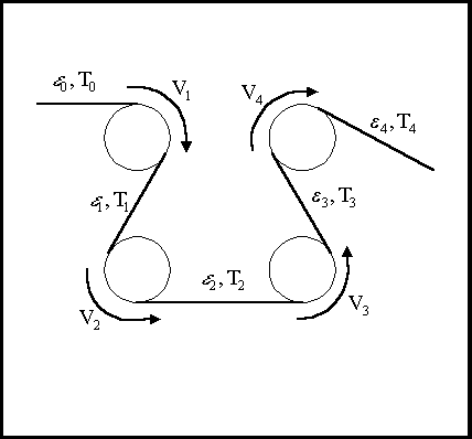
Figure 2 shows an example bridle section, consisting of four rollers controlling the direction in which the strip moves. The subsequent bending of the strip can be characterized by forward and reverse bending directions. For example, if the bending direction in which roller 1 (exhibiting velocity V1 ) moves the strip is called forward bending, then the bending direction in which roller 2 (exhibiting velocity V2 ) moves the strip is called reverse bending.

Figure 2. Example bridle (4-section) in a process line
Other investigators, primarily interested in tension leveling, have studied this bending process as it would apply to the steady-state case of passing over and under a series of rolls of the same radius. The bending losses reported represented that for the n-th pass from one roll to the next identical roll of reverse bend. Kinnavy [1] considered bending combined with tension high enough to elongate the center fiber, for an elastic, perfectly-plastic material. Patula [2] , also for an elastic, perfectly-plastic material, considered bending with tension stress levels from zero to yield and identified five distinct (steady-state) behaviors, from completely elastic to completely plastic. Misaka and Masui [3] presented an experimental equation for the effective radius of curvature (when the strip does not conform with the roll) and an analysis of combined bending and tension for material exhibiting a linear work-hardening stress-strain characteristic. Smith [4] considered the increase in bending moment required when deforming an elastic, perfectly-plastic material as a measure of the added roll force due to the plastic work when straining the outside and inside fibers during bending.
The purpose of this paper is the remove the steady-state limitation inherent in the previous work, by presenting a computer model that simulates the bending and straightening process on a roll by roll basis. The model will be useful in the design of tension bridle systems.
The balance of this report is divided into the following five chapters (followed by the bibliography):
- Chapter 1 : Nomenclature
- Chapter 2 : Describes the basic features of the bending process and presents thefundamental equations to be used by the models in subsequent chapters
- Chapter 3 : Presents a bending-loss model from the literature [2] which is based on a set of algebraic equations that are valid for the special case of steady-state bending over rolls of identical diameter in alternating forward andreverse directions. The basis of the model is developed through a specificexample illustrating a series of three bending and straightening operations.
- Chapter 4 : Presents a numerical model of the bending process which is consideredmore general and more flexible than an algebraic model requiring steady-state conditions to be valid. The material deformations and any losses are determined and updated on a roll-by-roll basis.
- Chapter 5 : Conclusions
CONCLUSIONS
A numerical model was developed for estimating roll-by roll bending losses and tension build-up required in strip material as it bends and straightens while traveling through a network of powered and unpowered rolls in a process line. It provides for the calculation of strip fiber deformation on a roll-by-roll basis beginning at the process line entry section, without restricting the analysis to steady-state or identical forward-reverse bending paths. Numerical model results agreed with results obtained from less-flexible algebraic-equation-based models, derived in this report and found in the literature.

|