PAPER No. 13
Designing a Dynamometer Test Stand
with an
Emulated Gasoline/Diesel Engine Power Source:
A White Paper.
Brian Thomas Boulter
Applied Industrial Control Solutions LLC
4597 E Sprague Rd.
Independence, OH, USA 44131
© ApICS ® LLC 2000
Introduction:
Currently, automotive industry Dynamometer applications that test drive-shaft components such as transmissions and/or differentials are deployed using the target application gasoline/diesel engine as the power source in the test bed. This is to ensure that the dynamics of the test stand during transmission shift testing and power cycles accurately simulate the expected dynamics the drive train will encounter during normal operation. An electric motor with a drive system is used to simulate loading conditions, such as wind & roll resistance, and the gravitational normal force that results from a simulation of vehicle conveyance over a grade.
This white paper describes a method that is currently deployed in an existing Mustang Dynamometer application. In this application an electric motor is used in place of a gasoline/diesel engine without any significant change in the dynamics of the test stand. For all intents and purposes the drive train under test experiences the same shaft torque dynamics in the test stand with the emulated engine, that it encounters using an actual engine. The benefits of such an approach are self-evident;
- No need to provide fuel supply and exhaust control systems.
- No need for expensive specialized fire safety systems..
- Less stringent OSHA safety standards.
- Quickly download a new engine model as needed, making the test stand flexible and useful for conducting "what if" testing scenarios of engine/drive-shaft pairings.
- Quick re-tooling for new test applications on an as-needed basis without the need to mechanically change the engine set-up.
Realizing the above benefits is contingent on designing a drive control system that satisfactorily emulates the non-linear behavior of the gasoline/diesel engine. This requires a mathematical model of the engine. The model should correctly emulate the non-linear torque/speed characteristics of the engine over the entire [rpm] range of the engine. Actual operator controls, such as an accelerator pedal position, or the pedal position output of an emulated cruise controller can also be included as inputs to the model if desired. The drive control system must also provide adequately responsive engine inertia emulation, to correctly emulate acceleration/deceleration times on the engine side of the transmission, when shifting gears in the transmission. The architecture of a drive control system that provides this capability is described in the following sections.
Dynamometer Test Stand System Architecture
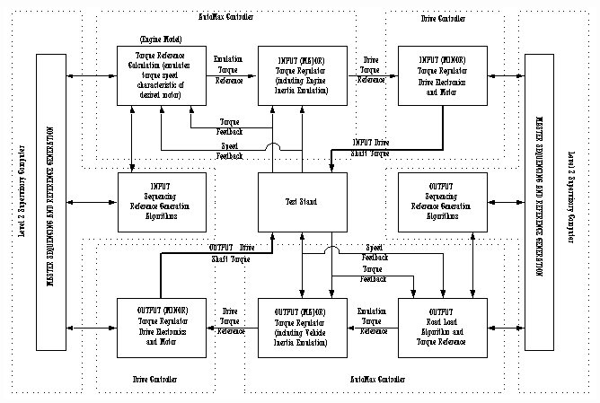
The architecture of the engine-less Dynamometer test stand is shown in Figure 1. The major elements of the system are described below.
Based on a given accelerator pedal position and an instantaneous INPUT stand shaft speed, the Engine Model in Figure 1. computes an instantaneous torque reference for the INPUT MAJOR torque regulator. The output of the INPUT MAJOR torque regulator produces a torque reference for the INPUT MINOR torque regulator, which, being a very responsive regulator, instantly produces the desired reference torque on the INPUT stand motor shaft.

Figure 1. Engine-less Dynamometer System Architecture
The INPUT MAJOR torque regulator is designed to be a low bandwidth regulator operating in parallel with a fast feed-forward reference to the high bandwidth INPUT MINOR torque regulator. It is coded in the Automax controller and includes a resonance compensating algorithm that assists in damping low frequency torsional resonances in the input drive-shaft. During speed changes in the INPUT stand drive shaft, an engine inertia emulation algorithm provides an additional torque reference that compensates for the difference between the INPUT stand electric motor inertia, and the desired emulated engine inertia. The inertia emulation algorithm utilizes a novel non-linear adaptive acceleration estimator that provides immunity to signal noise in the speed feedback. The INPUT MINOR torque regulator is a high bandwidth regulator that is coded in the INPUT motor drive. The drive and motor, in concert with the engine model and the MAJOR torque regulator, produce a drive-shaft torque (thicker line in Figure 1) that exhibits the same dynamic behavior as the modeled engine, thereby effectively replacing the engine with an electric motor.
Loading of the output stand is accomplished with a standard road-load algorithm. This algorithm in the Automax controller computes a load torque based on the following inputs:
- Rolling friction co-efficient.
- Grade.
- Effective vehicle frontal area (area times drag co-efficient)
- Vehicle mass.
- Stiction break force.
- Vehicle speed.
- Wind speed and direction
The computed torque from the road-load equation provides a reference to the OUTPUT MAJOR torque regulator. The OUTPUT MAJOR torque regulator is, like the INPUT MAJOR torque regulator, designed to be a low bandwidth regulator operating in parallel with a fast feed-forward reference to the OUTPUT MINOR torque regulator. It is also coded in an Automax controller and includes a resonance-compensating algorithm. Similar to the INPUT MAJOR torque regulator, an additional torque reference is provided that compensates for the difference between the OUTPUT stand electric motor inertia, and the desired emulated vehicle inertia during speed changes in the OUTPUT stand. The output of the OUTPUT MAJOR torque regulator produces a torque reference for the OUTPUT MINOR torque regulator, which is coded in the OUTPUT stand drive.
Referencing and Sequencing
Supervisory referencing and sequencing is handled in the Level 2 computer, which communicates with the Automax regulators and drives using standard communication protocols. Each application may require a custom communication package, and needs to be thoroughly investigated before proceeding with the design. Industry standard protocols are evolving at a brisk pace. Depending on the needs of the test set-up, the best communication package for each application must be identified prior to finilizing the design.
INPUT Stand Engine Model
The torque reference generated by the engine model algorithm is a function of the speed of the engine and a reference accelerator pedal position. An algorithm in the engine model computes the fuel rate for a given speed and pedal position. The fuel rate algorithm is limited by a look-up table that computes maximum fuel-rate for a given speed. The final torque reference to the INPUT MAJOR torque regulator is computed using a two dimensional look-up table that uses fuel-rate, and speed as inputs, and computes emulation drive-shaft torque as the output. The engine model is proprietary and not presented here in great detail. The model is designed to be generic enough such that downloading a target engine parameter set will enable the emulation of most engines. It is possible that some engines may require a different model.
INPUT Stand Drive System Controller Architecture
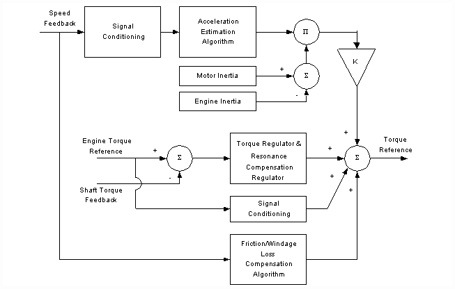
The block diagram below (Figure 2) describes the architecture of the INPUT MAJOR torque regulator. It is composed of three main sections:
- The engine inertia emulation feed-forward controller
- The resonance compensating torque regulator
- Friction/loss emulation (typically not required)
The inertia emulation algorithm computes the additional torque required to accelerate the electric motor so that, for a given shaft torque, the rate of change in shaft speed matches what can be expected in an application with the actual engine inertia. This is accomplished by computing the acceleration of the INPUT stand drive-shaft (i.e. the derivative of the speed feedback), scaling correctly, and then multiplying the computed acceleration by the difference between the electric motor inertia and the gasoline/diesel engine inertia. This is then added to the torque reference that feeds the INPUT MINOR torque regulator in the drive. In equation form this is expressed as:


Figure 2. INPUT MAJOR Torque Regulator Architecture
The greatest difficulty that is encountered in the design of any algorithm that estimates acceleration is its sensitivity to noise in the speed feedback. This is true for both state-space and simple derivative based solutions. A novel adaptive acceleration estimator is used to significantly reduce sensitivity to noise during normal operation. Briefly, the responsiveness of the acceleration estimation increases when the rate of change in speed increases, and drops off significantly when running at a steady speed. This allows for a very responsive estimation when it is needed, that is, when the shaft speed is changing. It does not however introduce amplified speed feedback noise into the torque loop when running the test stand at a steady speed.
The maximum ratio of electric motor inertia to emulated engine inertia, over which the inertia emulation algorithm has proven to be successful in the field, is currently 10:1, or:

Fast torque regulator response is accomplished by feeeding forward the torque reference from the Engine Model to the INPUT MINOR torque loop reference. The MAJOR Torque Regulator/Resonance-Compensator is tuned for a fairly slow integral response (to remove steady-state errors) and can be tuned to dampen low frequency torsional resonances, if they are problematic.
The friction/windage loss compensation algorithm can be set-up to provide compensation for "lossy" drive-train components as a function of shaft speed, if so required.
OUTPUT Stand Drive System Controller Architecture
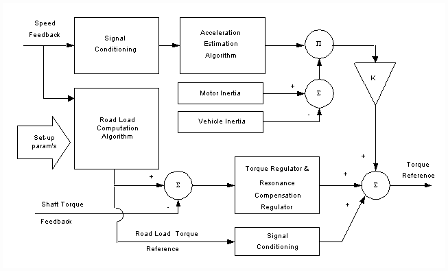
The block diagram below (Figure 3) describes the architecture of the OUTPUT MAJOR torque regulator. It is composed of three main sections:
- The vehicle inertia emulation feed-forward controller.
- The resonance compensating torque regulator.
- Road Load computation algorithm.

Figure 3. OUTPUT MAJOR Torque Regulator Architecture
Like the INPUT stand, the OUTPUT stand inertia emulation algorithm computes the torque required to accelerate the electric motor so that, for a given shaft torque, the rate of change in OUPUT shaft speed matches what is expected in an application driving the actual vehicle inertia. In equation form this is expressed as:

The novel adaptive acceleration estimator used on the INPUT stand is also used on the OUTPUT stand. Of interest to note is the fact that the reflected vehicle inertia will almost always be greater than the electric motor inertia. This implies that the vehicle inertia emulation reference of the OUTPUT stand will "resist" changes in speed, the greater the vehicle mass, the greater the resistance to a change in speed.
Care must be taken when calculating the reflected inertia of the vehicle. The following formula can be used to correctly compute this value (note: this equation neglects the inertia of the vehicle wheel)

Where, WV is the weight of the vehicle in [lbs], R is the radius of the vehicle wheel in [ft], GR is the differential power ratio, and Eff. is the efficiency factor for the differential. If the test-stand set-up includes the differential, GR and Eff. can be set to 1.
The maximum ratio of electric motor inertia to emulated vehicle inertia is currently 1:50. Therefore:

The torque reference from the road load equation is fed-forward to the high bandwidth INPUT MINOR torque loop reference. The Torque Regulator/Resonance-Compensator is tuned in the same way as the INPUT stand.
Conclusion:
A model based engine emulation strategy has been successfully applied at a Mustang Dynamometer customer site. This approach has greatly simplified the process of testing transmissions with multiple engines. This can now be done without the need to provide the actual engine, and the associated safety and support systems, and without the need to execute a mechanical change of the engine when testing the transmission with a different engine is required.
This method requires a satisfactory mathematical model of the target engine, and a responsive inertia emulation algorithm, both of which were demonstrated successfully at this site. This leap in Dynamometer test-bed technology will open the door to effective, efficient testing of drive-shaft components in any application that requires testing with shaft torque dynamics that closely mimic the "real-life" dynamics of the target application.
|