PAPER No. 3
Diameter Sizing of Rolls in Bridles That Utilize Powder Clutches
1996 IEEE IAS Annual Meeting
Brian Thomas Boulter
Applied Industrial Control Solutions LLC
4597 E Sprague Rd.
Independence, OH, USA 44131
© ApICS ® LLC 2000
Abstract - The use of powder clutches for regulation of torque in entry and exit bridles of tension levelers must take into consideration the constraints imposed by the slip requirements of the powder clutch. This paper provides guidelines for roll diameter sizing as a function of the maximum linear line speed and worst case application tension profiles such that the powder clutch always operates in a reasonable slip operating range.
Key Words: Bridles, Powder-Clutches, Tension Levelers, Strip Tension.
1. INTRODUCTION
Scratching of the strip observed during commissioning of the tension leveler of an OEM tension leveling line was attributed to slippage in the entry and exit bridles of the tension leveler.
Based on a careful analysis of the tension profiles, bridle roll static and dynamic friction coefficients, and motor power requirements of the entry and exit bridles of the tension leveler nothing was found to explain the observed bridle slippage. It became apparent that an additional "unknown" was responsible. To facilitate a better understanding of the problem a brief description of a powder clutch and the power transmission system of the OEM tension leveler is presented.

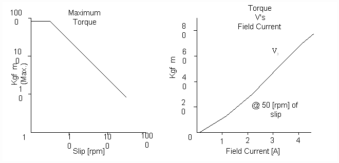
Figure 1. Typical Powder Clutch Performance Curves
A powder clutch is a passive device, it is incapable of supplying power to a system. Briefly, it is a type of electro-magnetic disk clutch in which the space between the clutch members is filled with dry, finely divided magnetic particles; application of a magnetic field coalesces these particles, creating friction forces between the clutch members. Shaft torque can be regulated by controlling the strength of the magnetic field, and hence the friction between the clutch members. Powder clutches are designed to operate with a fairly linear relationship between torque and field current within a given slip range (Fig. 1). the direction of power flow through the clutch is always from the shaft that is rotating faster to the shaft that is rotating slower.

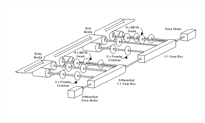
Figure 2. Mechanical Power Transmission Schematic of the Tension Leveler
Fig. 2. is a schematic representation of the power transmission system in the tension leveler. Beginning with the exit bridle, a drive motor provides power to the system through a 1:1 transmission. The output shafts of the exit bridle transmission are all rotating at the same speed. All four drive shafts feed power to the rolls through 96/16 gears. Power is supplied to the gear for roll #5 directly from the 1:1 transmission. For rolls #6, #7 and #8 power is supplied through individual powder clutches. Strip tension in each section of the exit bridle decreases between higher roll numbers, with a minimum at the exit of the exit bridle. The bridle is said to be "motoring", therefore power must be supplied to the process from the drive motor as indicated by the direction of the arrows representing the drive shafts. The amount of torque on the individual shafts determines the drop in strip tension across each roll and is controlled with the powder clutch field current.
Another motor is connected to a differential gear box. The differential gearbox is also connected to the 1:1 drive transmission to provide a path for power transmission from the entry bridle to the exit bridle. The differential configuration enables the average rotating speed of the entry bridle to be slightly less than the exit bridle thereby creating the necessary elongation for tension leveling. The output shafts of the entry bridle differential transmission are, like the shafts on the exit bridle, all rotating at the same speed. Similarly all four drive shafts feed power to the rolls through 96/16 gears. Power is supplied to the gear for roll #4 directly from the differential transmission. For rolls #1, #2 and #3 power is supplied through individual powder clutches. The tensions in each section of the entry bridle increase between higher roll numbers, with a maximum at the exit of the entry bridle. The bridle is said to be "regenerating", therefore power must be absorbed from the process to the drive motor as indicated by the direction of the arrows representing the drive shafts. Analogous to the exit bridle, the amount of torque on the individual shafts determines the tension increase across each roll and is controlled with the powder clutch field current.
In the entry bridle, roll #4 is not connected to a powder clutch therefore the [rpm] of the shafts on the differential transmission side of the powder clutches for rolls #1, #2 and #3 will rotate at the same speed as the drive shaft for roll #4. To satisfy the requirement that the process side powder clutch shafts rotate faster than the transmission side shafts (to absorb power from the process to the transmission) the roll diameters for rolls #1, #2 and #3 must be less than #4. A similar analogy can be drawn for the exit bridle showing that rolls #6, #7 and #8 must have larger diameters than roll #5.
The roll diameters on the commissioned leveler bridles were sized by the OEM such that the powder clutches operated with a very small slip (less than 0.1 [rpm]). This was done without consideration of the differential in adjacent roll surface speeds that is required to maintain a given strip tension (see [1], [2], [3]). An analysis of the entry bridle that included this phenomena revealed that at a given line speed the reduction in roll diameters of rolls #1, #2, #3 was not sufficient enough to guarantee that the process side powder clutch shafts would rotate faster than the transmission side shafts. Bridle behavior would be completely unpredictable at or above this speed.
Section 2 contains a derivation of a roll diameter sizing equation based on a commonly used strip tension dynamic equation. Section 3 closes with some conclusions.
3. CONCLUSION
When sizing the roll diameters in applications with powder clutches consideration must be made to provide a reasonable minimum slip in the powder clutch. In addition the velocity differential attributable to stretch in moving strip must also be accommodated.

| 