PAPER No. 3
Diameter Sizing of Rolls in Bridles That Utilize Powder Clutches
1996 IEEE IAS Annual Meeting
Brian Thomas Boulter
Applied Industrial Control Solutions LLC
4597 E Sprague Rd.
Independence, OH, USA 44131
© ApICS ® LLC 2000
Abstract - The use of powder clutches for regulation of torque in entry and exit bridles of tension levelers must take into consideration the constraints imposed by the slip requirements of the powder clutch. This paper provides guidelines for roll diameter sizing as a function of the maximum linear line speed and worst case application tension profiles such that the powder clutch always operates in a reasonable slip operating range.
Key Words: Bridles, Powder-Clutches, Tension Levelers, Strip Tension.
1. INTRODUCTION
Scratching of the strip observed during commissioning of the tension leveler of an OEM tension leveling line was attributed to slippage in the entry and exit bridles of the tension leveler.
Based on a careful analysis of the tension profiles, bridle roll static and dynamic friction coefficients, and motor power requirements of the entry and exit bridles of the tension leveler nothing was found to explain the observed bridle slippage. It became apparent that an additional "unknown" was responsible. To facilitate a better understanding of the problem a brief description of a powder clutch and the power transmission system of the OEM tension leveler is presented.

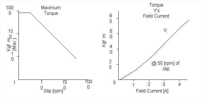
Figure 1. Typical Powder Clutch Performance Curves
A powder clutch is a passive device, it is incapable of supplying power to a system. Briefly, it is a type of electro-magnetic disk clutch in which the space between the clutch members is filled with dry, finely divided magnetic particles; application of a magnetic field coalesces these particles, creating friction forces between the clutch members. Shaft torque can be regulated by controlling the strength of the magnetic field, and hence the friction between the clutch members. Powder clutches are designed to operate with a fairly linear relationship between torque and field current within a given slip range (Fig. 1). the direction of power flow through the clutch is always from the shaft that is rotating faster to the shaft that is rotating slower.

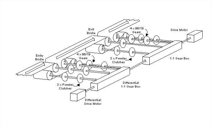
Figure 2. Mechanical Power Transmission Schematic of the Tension Leveler
Fig. 2. is a schematic representation of the power transmission system in the tension leveler. Beginning with the exit bridle, a drive motor provides power to the system through a 1:1 transmission. The output shafts of the exit bridle transmission are all rotating at the same speed. All four drive shafts feed power to the rolls through 96/16 gears. Power is supplied to the gear for roll #5 directly from the 1:1 transmission. For rolls #6, #7 and #8 power is supplied through individual powder clutches. Strip tension in each section of the exit bridle decreases between higher roll numbers, with a minimum at the exit of the exit bridle. The bridle is said to be "motoring", therefore power must be supplied to the process from the drive motor as indicated by the direction of the arrows representing the drive shafts. The amount of torque on the individual shafts determines the drop in strip tension across each roll and is controlled with the powder clutch field current.
Another motor is connected to a differential gear box. The differential gearbox is also connected to the 1:1 drive transmission to provide a path for power transmission from the entry bridle to the exit bridle. The differential configuration enables the average rotating speed of the entry bridle to be slightly less than the exit bridle thereby creating the necessary elongation for tension leveling. The output shafts of the entry bridle differential transmission are, like the shafts on the exit bridle, all rotating at the same speed. Similarly all four drive shafts feed power to the rolls through 96/16 gears. Power is supplied to the gear for roll #4 directly from the differential transmission. For rolls #1, #2 and #3 power is supplied through individual powder clutches. The tensions in each section of the entry bridle increase between higher roll numbers, with a maximum at the exit of the entry bridle. The bridle is said to be "regenerating", therefore power must be absorbed from the process to the drive motor as indicated by the direction of the arrows representing the drive shafts. Analogous to the exit bridle, the amount of torque on the individual shafts determines the tension increase across each roll and is controlled with the powder clutch field current.
In the entry bridle, roll #4 is not connected to a powder clutch therefore the [rpm] of the shafts on the differential transmission side of the powder clutches for rolls #1, #2 and #3 will rotate at the same speed as the drive shaft for roll #4. To satisfy the requirement that the process side powder clutch shafts rotate faster than the transmission side shafts (to absorb power from the process to the transmission) the roll diameters for rolls #1, #2 and #3 must be less than #4. A similar analogy can be drawn for the exit bridle showing that rolls #6, #7 and #8 must have larger diameters than roll #5.
The roll diameters on the commissioned leveler bridles were sized by the OEM such that the powder clutches operated with a very small slip (less than 0.1 [rpm]). This was done without consideration of the differential in adjacent roll surface speeds that is required to maintain a given strip tension (see [1], [2], [3]). An analysis of the entry bridle that included this phenomena revealed that at a given line speed the reduction in roll diameters of rolls #1, #2, #3 was not sufficient enough to guarantee that the process side powder clutch shafts would rotate faster than the transmission side shafts. Bridle behavior would be completely unpredictable at or above this speed.
Section 2 contains a derivation of a roll diameter sizing equation based on a commonly used strip tension dynamic equation. Section 3 closes with some conclusions.
2. ANALYSIS
2.1 NOMENCLATURE
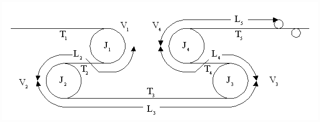
For the analysis the nomenclature is associated with the entry bridle model shown in Fig. 3
|
Ji |
The iíth roll inertia [kg m^2] |
|
Vi |
The iíth roll surface velocity [m/min] |
|
w i |
The i'th roll reflected rotational velocity [rpm] |
|
Ri |
The iíth roll radius [m] |
|
Di |
The iíth roll diameter [m] |
|
GRi |
The iíth roll gear ratio |
|
Li |
The iíth tension zone length [m] |
|
Ti |
The iíth tension zone tension [kgf] |
|
t i |
The iíth roll reflected shaft torque [kgf m] |
|
E |
Modulus of elasticity [kgf/mm^2] |
|
A |
Cross sectional area [mm^2] |
|
AMIN |
Minimum strip cross sectional area [mm^2] |
|
s |
The Laplace operator |
|
LS |
Maximum line speed [m/min] |
|

|
Slip at the iíth roll powder clutch [rpm] |
|
SI(MAX) |
Maximum powder clutch slip at the i'th roll [rpm] |
|
D TI(MAX) |
Maximum tension drop across the i'th roll [kgf m] |

Figure 3. Physical Bridle Model
2.2 STRIP TENSION VíS SPEED DIFFERENTIAL EQUATION:
The strip tension equation (1) is a commonly used representation ([1], [2], [3]) of the dynamics associated with the conveyance of strip through tension zones with the use of bridles. It is based on the concept of conservation of mass.
 ; (1) ; (1)
Assuming zero initial conditions, taking the Laplace transform of (1) and solving for Ti yields:
 (2) (2)
For metals applications it is reasonable to assume the Vi is approximately equal to Vi-1 [4], (2) can now be expressed as:
 (3) (3)
Solving (2) for the condition where Ti-1, Vi and Vi-1 are constant and assuming no disturbances, we can obtain an approximation of the speed differential required to maintain a specific tension (5):
 (4) (4)
Therefore:
 (5) (5)
Solving for Vi-1 we obtain:
 (6) (6)
Non-linear contributions such as strip viscous and square-law material damping have not been included in (6). Inclusion of these material properties would result in a speed differential other than that calculated with (6). With this in mind the analysis that follows should be viewed as ideal. Some margin to accommodate these exclusions should be left in the final design guidelines.
2.3 DESIGN RULES FOR ROLL DIAMETER CALCULATIONS IN POWDER CLUTCH BRIDLE APPLICATIONS
From (6) it is clear that the faster the line speed of a given application the greater the speed difference between two driven rolls must be to maintain a given tension differential ( ). In the OEM bridle design the values of GRi are equal to 96/19 on all the powder clutch torque controlled rolls, therefore ). In the OEM bridle design the values of GRi are equal to 96/19 on all the powder clutch torque controlled rolls, therefore  for a range of line speeds can only be achieved by either changing the speed of rotation of the driven roll and/or by change in the diameter of the roll. for a range of line speeds can only be achieved by either changing the speed of rotation of the driven roll and/or by change in the diameter of the roll.
As described in the introduction, for the entry bridle to regenerate power the powder clutch requires that the load side shaft be rotating faster than the motor side shaft. To accomplish this the OEM increased the diameter of the driven rolls as the strip passes through the bridle (i.e. D1 < D2 < D3 < D4 in Fig. 3). If we ignore the effect of stretch in the strip (Eq. 6) then with these diameters w1 > w 2 > w 3 > w 4 and the powder clutch slip should theoretically be in the correct direction. However when the effect of strip stretch (5) is considered there now exists the possibility that the additional velocity differential term may result in a condition where w1 < w 2 < w 3 < w 4 to maintain tension in the strip. This is a physically unrealizable operating condition for the powder clutch. The entry bridle can no longer regenerate power through the powder clutches and the tension in the strip will not follow the desired tension profile. The bridle behavior is no longer predictable. A similar analogy exists for the exit bridle.
The purpose of the following analysis is to identify maximum bridle roll diameters such that w1 > w 2 > w 3 > w 4 for all strip cross sectional areas, all line speeds, and all bridle tension profiles. An analysis for the entry bridle roll diameter calculations is presented, the exit bridle roll diameters are calculated with a similar procedure.
The following constraints need to be identified for the analysis:
- Identify the maximum slip desired in the powder clutch: (S(MAX))
- Identify the maximum possible tension drop requirement of the driven rolls. (DT(MAX) )
- Identify the minimum strip cross sectional area. (AMIN)
Let the rotational speed of the shaft on the motor side of the 96/16 gear-box for the speed regulated driven roll is given as:
 (7) (7)
Then the entry bridle analysis begins at the speed regulated roll (Roll #4) and moves out toward the entry bridle entry roll (Roll #1). The equations governing the rotational speeds of the these rolls are obtained by combining (6) and (7):
 (8a) (8a)
 (8b) (8b)
 (8c) (8c)
To meet the minimum slip requirement the analysis should be performed for the worst case scenario. That is for a minimum cross sectional area, maximum  's and the desired 's and the desired  . This may be accomplished by solving (8a,b,c) for the roll radius and these operating conditions. That is: . This may be accomplished by solving (8a,b,c) for the roll radius and these operating conditions. That is:
 (9a) (9a)
 (9b) (9b)
 (9c) (9c)
The worst case analysis above has a built in safety margin based on the use of a minimum cross sectional area with an unrealistic tension differential through the bridle. However this approach provides for accommodation of the unmodeled non-linearities described in section 2.2 above and leads to a more robust design. A more general form of (8,a,b,c) for n rolls (where the n'th roll is speed regulated and the other rolls are driven through powder clutches) can be expressed as:
 (9d) (9d)
Similar derivations can be made for the exit bridle where, in terms of flow, the first roll in the bridle is speed regulated:
 (10a) (10a)
 (10b) (10b)
 (10c) (10c)
Table 1. contains a calculated set of diameters based on a set of parameters for the entry bridle at the OEM's user site. The author used a Si(MAX) of 3 [rpm]. This value was chosen based on the advice of several powder clutch vendors who recommend operating the powder clutch with as much slip as an application will allow. This is to avoid erratic torque behavior that occurs when operating with slips that approach zero. This erratic behavior is attributed to a vacillation of the friction coefficient between the powder in the clutch and the rotating surfaces. With extremely low slip values the friction coefficient randomly varies from a static value (when the input and output speeds lock together) to a dynamic value (when there is slight slip in the powder clutch). However it should be pointed out that the amount of maximum slip in the powder clutch must also be chosen based on a careful analysis of the thermal characteristics of the powder clutch and the desired application torque for the clutch. This is to avoid overheating during normal operation.
| |
Roll #4 |
Roll #3 |
Roll #2 |
Roll #1 |
|
LS [m/min] |
600 |
600 |
600 |
600 |
|
AMIN [mm^2] |
144 |
144 |
144 |
144 |
|
E [kg/mm^2] |
21000 |
21000 |
21000 |
21000 |
|
D Ti(MAX) [kg] |
8009 |
4622 |
2667 |
1539 |
|
GRi |
96/19 |
96/19 |
96/19 |
96/19 |
|
SMAX [rpm] |
0 |
3 |
3 |
3 |
|
Di [m] |
1.00014 |
0.99552 |
0.99464 |
0.99413 |
Table 1. Entry Bridle Roll Diameters
D Ti(MAX) was calculated using 2100 [kg] entry tension maximum, a coefficient of friction  for the rolls equal to 0.15 and a wrap angle of 210 [deg] on each roll as follows: for the rolls equal to 0.15 and a wrap angle of 210 [deg] on each roll as follows:

For the exit bridle:
| |
Roll #5 |
Roll #6 |
Roll #7 |
Roll #8 |
|
LS [m/min] |
600 |
600 |
600 |
600 |
|
AMIN [mm^2] |
144 |
144 |
144 |
144 |
|
E [kg/mm^2] |
21000 |
21000 |
21000 |
21000 |
|
D Ti(MAX) [kg] |
-12687 |
-7321 |
-4225 |
-2430 |
|
GRi |
96/19 |
96/19 |
96/19 |
96/19 |
|
SMAX [rpm] |
0 |
3 |
3 |
3 |
|
Di [m] |
1.00055 |
1.00124 |
0.99984 |
0.99904 |
Table 2. Exit Bridle Roll Diameters
D Ti(MAX) was calculated using 30000 [kg] entry tension maximum, a coefficient of friction  for the rolls equal to 0.15 and a wrap angle of 210 [deg] on each roll as follows: for the rolls equal to 0.15 and a wrap angle of 210 [deg] on each roll as follows:

3. CONCLUSION
When sizing the roll diameters in applications with powder clutches consideration must be made to provide a reasonable minimum slip in the powder clutch. In addition the velocity differential attributable to stretch in moving strip must also be accommodated.
References
[1] Carter, W. C., "Reducing Transient Strains in Elastic Processes" , Control Engineering Mar. 1965. pp. 84-87.
[2] Boulter, B. T., "A Novel Approach for On-Line Self-Tuning Web Tension Regulation ", Proceedings of the 4th IEEE International Conference on Control Applications, pp 91-98, September 1995.
[3] Fox, S. J., Lilley, D. G., "Computer Simulation Of Web Dynamics ", Proceedings of the 1st IWHC International Web Handling Conference Tab 20. Oklahoma State University, March 1991.
[4] Hamby, R. C., "SER # 35, Tension Regulation" , Reliance Electric Engineering Reports 1968.
|