FIELD SERVICE REPORT No. 39
|
To: |
(Proprietary) |
|
From: |
Brian Boulter - Chief Consulting Engineer |
|
Date: |
February 24th 2000 |
|
Subject: |
Field Trip Report, Rodney Telledyne, New Bedford Ma. |
Introduction
The author made a field trip to the Rodney Telledyne Z-Mill plant at New Bedford Ma. to address an instability problem in the winder/unwinder tension loops. The instability was reported to occur with stainless material at surface speeds of 500 700 [ft/min], during machine accelerations and decelerations, and was responsible for strip breaks with light materials (less than 0.004"). In addition the problem always occurred on the side of the mill where the empty core was located (i.e. the winder if accelerating, or the unwinder if decelerating).
The instability can be described as a dip in tension followed by an overshoot, that the tension loop takes approximately 2 5 [sec] to recover from. For thicker material the recovery is faster than it is for thinner material. This indicates that the bandwidth of the tension regulator is not consistent over the product range. In terms of magnitude, the tension dip varies from the set-point by +1000 to - 2000 [lb]. With thicker material this is not a problem, however, with the thinner materials (cross-sectional areas of approximately 0.05 0.1 [in ^2]) the resulting change in tensile strain can be as high as +20,000 to -40,000 [psi]. When added to the working tension (about 45,000 60,000 [psi]), the tension overshoot can easily exceed the tensile strength of the material and result in a strip break.
A quad loop tension regulator configuration is deployed on the winders for this machine. The tension loop PI output feeds a trim to a current major loop. The current major loop PI output feeds a trim to a speed loop. The speed loop PI output feeds a reference to a current minor loop. Because of the ease with which this configuration could be switched in and out with a current regulator, this configuration was popular in the days of analog control.
The trip was made to the site on 2/15/00 2/18/00. The following observations and corrective actions were taken.
Observations:
While on-site no thin material was run through the machine. The lightest gauge that was run through the mill was a final pass of 0.008", and no strip breaks were observed. However, a set of "service-max" chart recordings made during the trip, caught the main attributes of the problem (Figures 1 through 8, located at the end of this report). After assessing the charts, and observing the mill during normal operation, the following observations were made:
- The operator that reported the problem was observed to accelerate and decelerate the mill in increments. Letting the mill run at an interim speed while allowing the tensions to stabilize before continuing on to a higher or lower speed. (As shown in Figure 5, the mill was accelerated to approx. 600 [fpm] and allowed to settle. Note the dip in tension occurs after the acceleration)
- The Diameter calculation was halted during acceleration and/or deceleration, and re-enabled when acceleration or deceleration was completed. This was accomplished in the ladders using a bit that was true whenever line reference rate was non-zero. i.e. disable the ratio detector whenever that bit was true (see Figures 4. and 5. L_RPM_FDBK, R_DBAR_I, and L_DBAR_I)
- After accelerating, the ratio detector was re-enabled and the diameter computation ramped up to the correct diameter. When accelerating from core, the rate of change in diameter can be substantial. For example, at the end of a full acceleration, the calculated diameter from the ratio detector would ramp from 24" to approximately 25.5" (Figure 4. R_DBAR_I).
- The shunt field in this application is set to match diameter. At core, small changes in field current result in large changes of shaft torque per-stator-amp, when compared to the same changes at full roll. The field current was being set by a function table with diameter (D_Bar_I) as a pointer. Because the pointer into the field table was fixed at 24" during acceleration, it was clear that, while accelerating, the expected torque per-amp and the actual torque per-amp of the winder/unwinder did not agree. In an attempt to compensate for this, the tension regulator provided a growing positive offset (out of the tension loop PI) to the trim output during acceleration (see Figure 2. R_T_LOOP_OUT). The same observation was made during decelerations, with the exception that the offset grew in the negative direction. (Note that when winding, an increase in tension vernier output will tend to speed the winder up)
- During acceleration, the output of the current major loop PI was observed to dip (see Figure 2. R_C_LOOP_OUT), This was to be expected, given that the diameter (R_DBAR_I) was not being correctly computed. The conversion from per-normal translational speed [ft/min] to per-normal rotational speed [rpm] is accomplished by dividing the summation of line speed reference and the vernier from the current major loop, by diameter. During acceleration, to maintain the desired tension in the strip, the speed reference in per-normal [ft/min] needed to be reduced by an amount that produced the desired reference in per-normal [rpm]. This offset amount is reflected in the vernier trim from the current major loop (R_C_LOOP_OUT). Based on this observation, the current major loop integrator was being "wound-up" (in a negative magnitude) during accelerations, to a magnitude that was incorrect for steady state running conditions.
- During the end of the acceleration, when the s-curve is reducing the rate of change in speed to zero, the inertia compensation signal reduces to zero (Figure 6. R_WR2_COMP). At this point the tension begins to dip (Figure 6. R_LG_TEN_FDBK). This is because the combination of incorrect diameter computation, incorrect inertia compensation (WR2_COMP_I is a function of D_BAR_I and F_BAR_I), and incorrect torque per-amp on the motor shaft results in a shaft torque that is too low to maintain the desired tension. The tension regulator attempts to compensate for the drop in tension and the PI output integrates up (Figure 2. R_T_LOOP_OUT).
- When the ratio detector is enabled at the end of an acceleration/deceleration, the rapid change in the computation of the roll diameter (as the ratio detector diameter calculation ramped up/down to the correct value) results in the tension increasing to the desired set-point. This is the result of the combination of the diameter pointer into the field table producing the expected torque per-amp on the motor shaft, and the tension loop PI regulator compensating for the offset. It can be seen that when the diameter recovers to the correct value, the tension also recovers to the correct value (Figures 2 and 4).
- The installed tension regulator has very little phase margin at core with light materials, therefore the regulator tends to overshoot when recovering from the observed dip in tension, The overshoot is minimal with thicker materials. It is this overshoot that led to the strip breaks.
Conclusions:
- The source of the problem is the way in which the diameter is being calculated. The diameter computation was clamped during acceleration and deceleration, and allowed to ramp up/down to the correct value several seconds after the acceleration/deceleration stopped. The reasoning behind this was to avoid erratic computation of diameter during acceleration/deceleration that resulted from slip on the billy-roll with thin materials at core.
- The problem was exacerbated with thin materials due to the loss of phase margin in the tension regulator with the thinner materials, and higher line speeds.
- To minimize the tension dip when exiting an acceleration/deceleration, diameter calculations must be made during accelerations and decelerations of the mill. The use of the billy roll for surface speed feedback is not a viable option due to slippage at light tensions and minimal wrap angles. An alternate approach is to use the draft compensated line speed reference for the mill during accelerations and decelerations, and switch to billy roll feedback several seconds after the acceleration/deceleration has completed.
- The operators must enter the correct roll diameters and reduction through the mill if the draft compensated feedback is to be used for the ratio detector during acceleration/deceleration of the mill.
Corrective actions, Software revisions:
- The CML bandwidths were set for 300 [rad/sec], this is the maximum value, and not a requirement in this application, to reduce wear on the motor brushes, and to soften the CML response, the CML bandwidth was reduced to 200 [rad/sec], which is the standard bandwidth for these applications
- The Tension loop was observed to be very hot, and even tended towards instability with some materials, to increase phase margin in the loops the tension loop gain was reduced from 5.0 to 2.5 on both reels.
- To minimize the tension dip when exiting an acceleration/deceleration, a diameter calculation was programmed to be made using the draft compensated line speed reference for the mill during accelerations and decelerations, and timers were put in to switch the surface speed feedback in the ratio-detector to billy roll feedback several seconds after the acceleration/deceleration has completed.
Conclusions:
No thin material was run while on site, so the effectiveness of the corrective actions was not able to be assessed. It was noted that the diameter computation was incorrect when the operator did not use the correct initial roll diameter or when draft was not being computed correctly. It is expected that the mill operation should be improved, and at the least the source of the problem is understood, and other corrective actions can be explored if needed.
Feedback on the mills operation would be greatly appreciated.
The following traces are included in Figures 1 through 9: They are for an accelerating mill winding on the right reel, unwinding on the left reel.
Figure 1
L_TEN_FDBK1 Left reel tension feedback (unfiltered)
L_C_LOOP_OUT Left reel Current loop PI output
L_T_LOOP_OUT Left reel tension loop PI output
L_LP_OUT Left reel speed loop PI output
Figure 2
R_LG_TEN_FDBK Right reel tension feedback (unfiltered)
R_C_LOOP_OUT Right reel Current loop PI output
R_T_LOOP_OUT Right reel tension loop PI output
R_LP_OUT Right reel speed loop PI output
Figure 3
L_IF_FDBK Left reel field current feedback (unfiltered)
L_LG_TEN_FDBKLeft reel tension feedback (unfiltered)
L_DBAR_I Left reel diameter calculation
L_CML_REF Left reel CML reference
Figure 4
R_DBAR_I Right reel diameter calculation
R_LG_TEN_FDBK Right reel tension feedback (unfiltered)
R_CML_REF Right reel CML reference
R_IF_FDBK Right reel field current feedback (unfiltered)
Figure 5
L_WR2_COMP Left reel Inertia compensation
L_LG_TEN_FDBK Left reel tension feedback (unfiltered)
L_DBAR_I Left reel diameter calculation
L_RPM_FDBK Left reel [rpm] feedback
Figure 6
R_WR2_COMP Right reel Inertia compensation
R_LG_TEN_FDBK Right reel tension feedback (unfiltered)
R_DBAR_I Right reel diameter calculation
R_RPM_FDBK Right reel [rpm] feedback
Figure 7
L_LG_TEN_FDBK Left reel tension feedback (unfiltered)
R_LG_TEN_FDBK Right reel tension feedback (unfiltered)
L_ARM_IFB Left reel current feedback (unfiltered)
R_ARM_IFB Right reel current feedback (unfiltered)
Figure 8
L_LG_TEN_FDBK Left reel tension feedback (unfiltered)
R_LG_TEN_FDBK Right reel tension feedback (unfiltered)
L_ARM_VFB Left reel voltage feedback (unfiltered)
R_ARM_VFB Right reel voltage feedback (unfiltered)
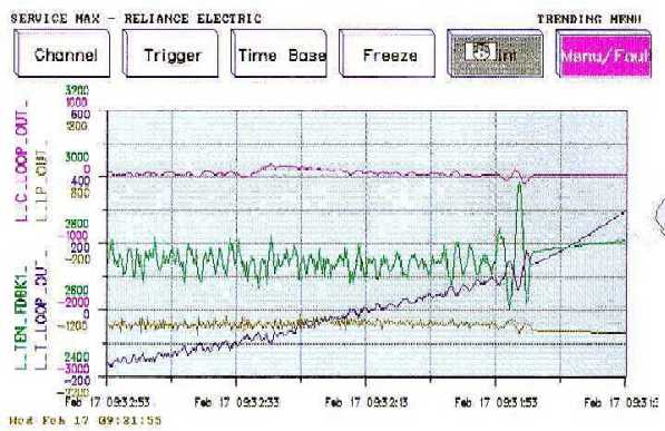
Figure 1.
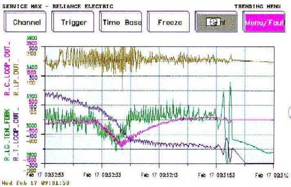
Figure 2.
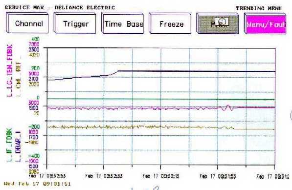
Figure 3.

Figure 4.

Figure 5.
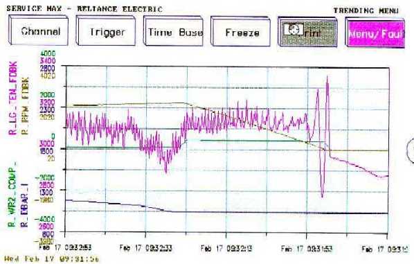
Figure 6.
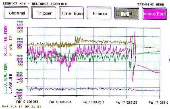
Figure 7.

Figure 8.
|
