PAPER No. 6 SUMMARY
Improving Bridle Low-Speed Regulation Using Cascaded Current Followers
1998 IEEE IAS Annual Meeting
Brian Thomas Boulter
Applied Industrial Control Solutions LLC
4597 E Sprague Rd.
Independence, OH, USA 44131
© ApICS ® LLC 2000
Abstract - The torque or current references to the current loops of drives providing power to helper-rolls in bridles are usually slaved directly from the current reference of the master speed regulated roll. At low line speeds the current required to overcome losses in the master speed regulated roll will differ significantly from the current required to overcome losses in the helper-rolls, resulting in overall erratic speed regulation in the bridle. A scheme based on cascaded current major loops is described and shown to provide a substantial improvement in low-speed regulation. An additional benefit is that higher speed-loop bandwidths are made possible by the de-coupling effect provided by the cascaded current major loop.
1. INTRODUCTION
Bridles function as tension amplifiers or line-speed pacers in metal strip process lines. The typical speed regulated bridle consists of several rolls each of which is driven by an individual power source. One of the rolls in the bridle is speed regulated. The other rolls in the bridle are operated as open-loop current followers that follow the current reference generated by the speed regulator (Figure 2). By slaving the helper-roll current references from the current reference generated by the speed regulator, each roll load-shares according to a predetermined ratio. The load-sharing ratios are a function of motor horse-powers, roll diameters [1], and gear-ratios. In some applications fine tuning of load-sharing is accommodated by individual gains on the current references.
In applications where low-speed bridle speed regulation can have a strong impact on the quality of the processed strip, it is imperative that the bridle helper-rolls and the speed-regulated roll operate with little or no relative deviation in speed. The following is a good example of an application that has such a requirement.
Assume that, because of space constraints, it is not possible to furnish accumulators in an independent tension leveling line. The line operates with a maximum line-speed of 1500 [ft/min] and is used to pre-process aluminum strip in preparation for painting. A requirement for continuous operation is the result of a market need to manufacture custom coil sizes for small volume buyers. A plausible solution is to operate the line at very low speeds (1 to 3 [ft/min]) and let the strip accumulate in a small loop when a coil change must be made. To avoid marking the strip in the leveler when operating at low speeds precise regulation of entry and exit bridle speed is required over a 1500:1 range. Precise entry and exit speed regulation at the low end of a large speed range is only possible if the entry and exit bridle helper-rolls and respective speed regulated rolls operate with no relative speed deviations.
A diagram of a typical 4-roll bridle is presented in Figure 1. Figure 2 shows a single-line diagram of the control structure of a 4-roll speed regulated bridle. In this example, the output of the speed minor loop (SML) of roll 4 provides the current references to the 4 current minor loops (CML’s). The SML regulates the speed feedback w4 to match the speed reference wREF
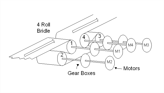
Figure 1. A Typical 4-Roll Bridle
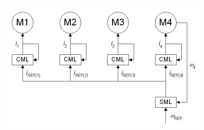
Figure 2. Single-Line Diagram of a Typical 4-Roll Bridle.
For many applications the control topology in Figure 2 is adequate. However, for extremely low-speed bridle applications such as that described above, this architecture will not provide satisfactory speed regulation. An explanation for this can be given in terms of the differences in system losses that occur from one bridle roll to the next.
The majority of system losses that occur in the drive trains and motors of a bridle can be lumped into the following friction classes: 1) viscous friction (BV), 2) coulomb friction (BC) 3) static friction or stiction (BS), and 4) square-law windage losses (BW). A popular equation ([2],[3]) combining these losses into an expression for the loss-torque in a drive is:
 (1) (1)
Plotting equation (1) results in a torque loss characteristic curve similar to Figure 3.
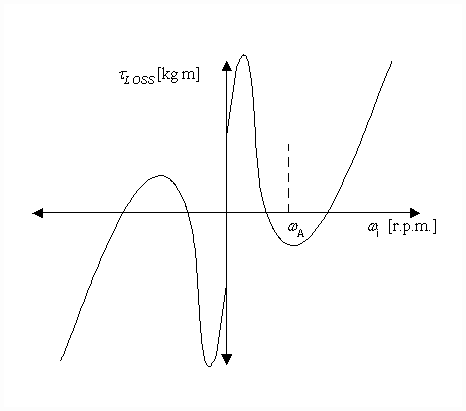
Figure 3. Bridle Roll Torque Loss Characteristic Curve
Each driven roll in the bridle will have differing values of BV, BC, BS, and BW. This results in differing torque loss characteristic curves from one helper-roll to the next.
Very low tension drops across bridle rolls can occur in some applications. This may require the drives to operate with very low drive currents, and, as a result of the extremely non-linear relationship between current and torque that transpires when DC drives operate in the discontinuous conduction region or AC drives operate with small Iq currents, a significant difference in the actual torque from the desired torque can result. This implies that a feed-forward current reference will not always produce the desired torque, and hence, the desired speed in the driven roll
The relationship between torque and speed in a bridle roll is given by equation (2) and the block diagram in Figure 4.
 (2) (2)

Figure 4. Block Diagram of Motor Torque-Balance Equation
If we assume that there is no strip attached to the driven roll (i.e. the strip tensions equal zero; Ti+1 = Ti = 0) and ‘n’ rolls are considered, it is clear from (2) that, for a common motor toque ti and inertia Ji for all ‘n’ rolls, the speed of each roll will depend on the integral of the system losses. Assuming, as described above, the value of tLOSS in each section differs, then as the ratio of tLOSS to ti increases, a more pronounced difference in speed between each driven roll will be observed.
From the above description of the typical bridle control topology it is clear that, at low speeds and low values of load torque {(Ti+1 - Ti)*Ri/GRi)}, the ratio of tLOSS to ti can be high enough to create a condition where the speeds of the rolls in the bridle will differ significantly. This occurs as periodic abrupt excursions of speed from zero to a value greater than the line-speed set-point as the driven rolls move in and out of their respective static friction regions. For most metal application bridles, the speeds at which this occur are below 1 [m/min]. Figure 5 is a plot of measured currents and speeds for a 4 roll entry bridle in a tension leveler, configured as shown in Figure 2, with a line speed set-point of 2/3 [m/min] (2 [ft/min]).
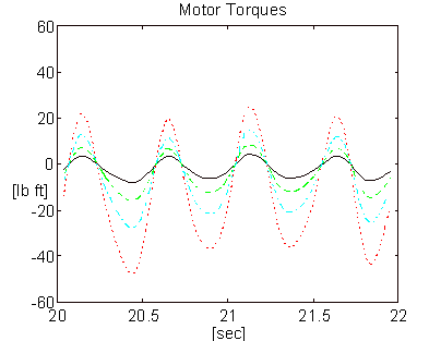
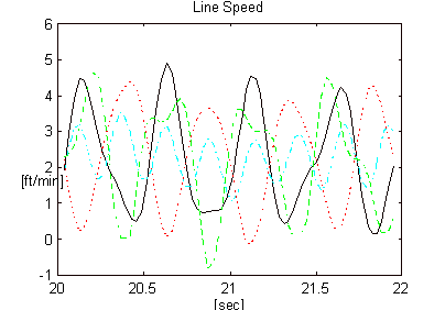
Figure 5. Measured Speeds and Currents of a 4-roll Bridle, Configured as Shown in Figure 2, Operating at a Low Speed.
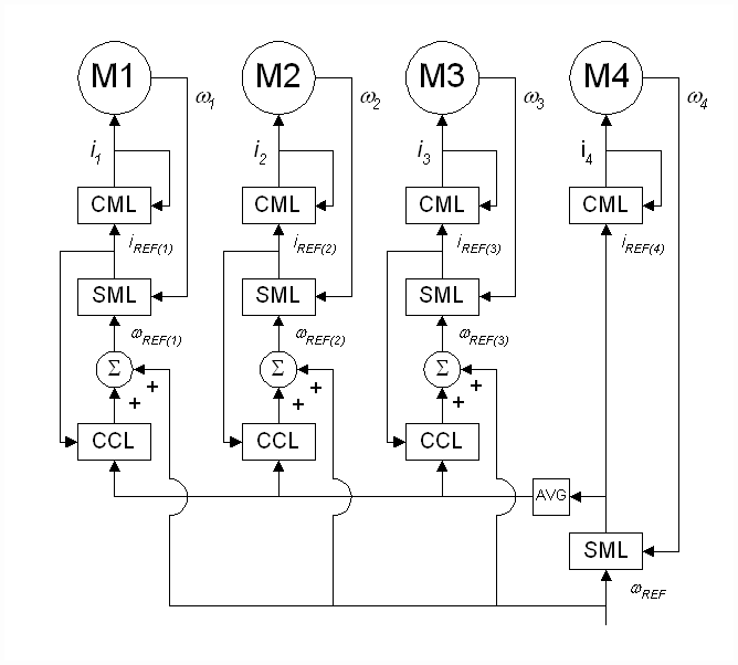
Figure 6. Proposed Bridle Control Topology
A significant improvement in low-speed speed regulation can be realized by cascading a current major loop with a speed-loop. A single-line diagram of the proposed control topology is presented in Figure 6. The output of the cascaded current-loop (CCL) provides a trim to the speed reference for the speed minor loop (SML) of each roll. The bandwidth of the CCL is designed such that it is at least 10 times less than the bandwidth of the CML. The assumption that the CML is an order of magnitude more responsive than the CCL ensures that the command reference to the CML will be approximately equal to the actual current. Given that the command reference to the CML is the output of the SML, the SML output can be used, in place of the measured current feedback, as the current feedback for the CCL. This is highly desirable in applications where the actual current feedback is small enough to be significantly corrupted by noise.
The improvement in speed regulation is realized by utilizing individual speed-loops for each driven roll. The speed-loops provide a way to compensate for the losses in each roll on a roll-to-roll basis and ensure that there will be little relative deviation in roll speed throughout the bridle over the full line speed range.
The remainder of the paper can be summarized as follows: Section two contains an analysis of the tuning strategy for the CCL. In addition, a description the de-coupling effect afforded by cascaded current-loops is provided. The third section presents results from a field trial, the fourth section provides some concluding remarks.
3. FIELD TESTING RESULTS
An O.E.M. tension-leveling line entry bridle on a tension-leveler was configured for operation with both architectures (Figures 2 and 6). The motor torque was calculated from armature current and filtered through a 2-pole Butterworth filter with a corner frequency of 62 [rad/sec] (10 [Hz]). The line speed was calculated from speed feedback [r.p.m.] and also filtered through a 10 [Hz] 2-pole Butterworth filter. 12 [mill] x 36 [in] aluminum strip was processed through the leveler at 2 [ft/min]. Figures 15 and 16 represent speed and torque for the architecture in Figure (2). Figures 17 and 18 represent speed and torque for the architecture in Figure (6).
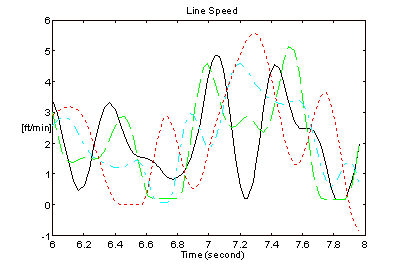
Figure 15. Line Speeds - Figure 2 Architecture
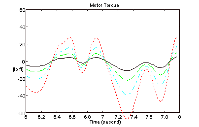
Figure 16. Motor Torques - Figure 2 Architecture

Figure 17. Line Speeds - Figure 6 Architecture
The bandwidth of the speed regulator driving roll 4 for the results in Figures 15 and 16 was approximately 10 [rad/sec]. The bandwidth of the speed regulators on all 4-rolls for the results in Figures 17 and 18 was approximately 30 [rad/sec]. The improvement in speed regulation is clearly evident when the CCL architecture is employed.
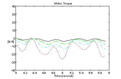
Figure 18. Motor Torques - Figure 6 Architecture
4. CONCLUSIONS
Significant improvements in bridle speed-loop bandwidths and speed regulation can be realized with the CCL architecture in multi-roll bridles. It is not unrealistic to expect a 3 to 4 fold increase in speed-loop bandwidth, drive-train integrity permitting, over those possible with the architecture presented in Figure 2. For bridle applications where excellent low-speed regulation is critical to product quality, the CCL architecture should be considered.

|