PAPER No. 10
Applying Drive Specifications to Systems Applications:
Part II: Current/Torque Regulation
2001 IEEE IAS Annual Meeting
Brian Thomas Boulter
Applied Industrial Control Solutions LLC
4597 E Sprague Rd.
Independence, OH, USA 44131
© ApICS ® LLC 2000
Abstract- In web handling & strip processing lines, a popular control practice is to use torque/current regulators to set web/strip tension. In other applications such as automotive test stands, a fast responsive torque regulator is required. This paper provides guidelines for the useful interpretation of AC/DC torque/current performance specifications in these applications, from a drive systemís application perspective.
I. Introduction
As noted in [3] the technical climate in todayís drive systems business markets has been inundated by drive vendor claims of ever improving drive performance specifications. The objective of this report is to bring those performance specifications that apply to torque/current regulation into technical focus, and provide the reader with a basis for correctly interpreting them from a SYSTEMS /APPLICATIONS perspective. Future papers will address performance issues associated with "cascaded" and "parallel", position and tension regulation schemes. Part I [3] dealt with speed regulation issues.
It is hoped that the reader will walk away from this presentation with the tools required to sift through a given driveís performance specifications, and glean from them those points that are truly of importance to the application in question.
- Paper Overview
The paper is divided into four sections. The first section is composed of this introduction, the second section defines a set of useful terms, the third section defines the most important drive specifications with respect to torque and current regulation, and methods of determining these criteria for a given drive. A set of observations and conclusions are presented in the fourth section
II. Some Useful Definitions
Two definitions that prove useful in understanding a drive system torque/current regulation performance criteria are, control loop bandwidth, and per-normal Inertia.
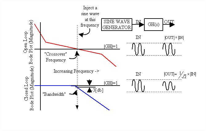
Control Loop Bandwidth (Fig. 1): Bandwidth is defined as the frequency at which the closed loop response of the controlled variable is attenuated 3 [db] from the set point. It is also approximated as the point at which the open loop gain of the system is unity and is called the "crossover" frequency. The Bode plot graphically represents the magnitude and phase of the ratio of output to input over a range of input frequencies. Therefore, unity gain of the system at the crossover frequency implies that, at that frequency, the output and the input of the open-loop system are equal in magnitude. And at all frequencies below this frequency, the closed loop has unity gain.

Fig. 1. Bandwidth Definition
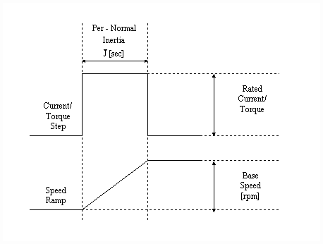
Per-Normal Inertia (Fig. 2): Per-normal (PN), or normalized, reflected inertia [sec] is the time in seconds that it takes to accelerate the motor and load inertia from zero speed to motor base speed (Sb) with motor rated torque (tRated) and the given reflected inertia (J).

Fig. 2 Per-Normal Inertia [sec]
SI units:  (1) (1)
III. Interpreting Drive Performance Torque/Current Specifications
A. Architecture Description
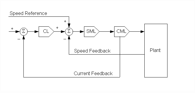
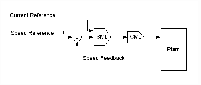
Current/torque regulators can be implemented as either cascaded or parallel major loops. The cascaded architecture (Fig.3) is implemented with a speed intermediate loop (SML). In this architecture, the current loop (CL) trims the SML which provides a reference to the current/torque minor loop (CML). The parallel architecture (Fig.4) provides a trim for the current/torque major loop directly to the CML, usually through the appropriate SML PI limit. By applying the control signal through the SML PI limit, the drive will not over-speed the motor if a strip or web break occurs during operation. Rather the drive will allow the motor to rotate at the given speed reference plus a small offset that is used to force the SML PI up against the limit.

Fig. 3. Cascaded Current/Torque Architecture.

Fig. 4. Parallel Current/Torque Architecture.
These regulation architectures are often used as a way of setting strip/web tension in strip/web processing lines without the need to close a tension loop around a load-cell tension feedback device. They are sometimes called open-loop tension regulators. Specifications that apply to the ability of the drive to set tension in these applications assume that inertia and friction/windage feed-forward compensation have been implemented and calibrated correctly. The tension "error" is then a function of the driveís current/torque linearity and the torque resolution. Following is a description of the feedforward terms.
IV. Observations and Conclusions
From the discussion in the previous sections it is clear that, for applications where regulating the torque level is critical, care should be taken to ensure that the AC or DC drive/motor combination is selected to meet the system performance requirements using the described methods. In particular, the drive linearity over the operating range, and the torque resolution should be verified as sufficient for the given application. In applications where the torque response is critical, and the torque level is not an issue, the bandwidth or step response data of the AC or DC torque loop should be used as a guide.

|